
Summary of Contents for Ewellix Telesmart TXG Series
- Page 1 CAT E G O R Y M A X 2 L I N E S I N S TA L L AT I O N , O P E R AT I O N A N D M A I N T E N A N C E M A N UA L Telesmart TXG Telescopic pillar...
-
Page 3: Table Of Contents
Contents 6.4 Connect to the control unit ........... 17 6.5 Connection to operating element ......... 17 6.5.1 Connect TXG10 (stand alone) to operation element .. 6.5.2 Connect TXG (all types except TXG10) to operating element ................17 1.0 General information ............4 6.6 Connect to power supply .......... -
Page 4: General Information
Te l e s m a r t T XG 1.0 General information DANGER 1.1 Information in this Indicates a dangerous situation, which will lead to death or serious personal manual injury, if the precautionary measures are ignored. This manual provides important information on how to work with the actuator (also called device) safely and efficiently. -
Page 5: Limitation Of Liability
In case the actuator is customised, the actual product deliv- new information and experience gained from practical appli- ered may be different from what is described in the manual. cation: such information and experience may help improve In this case, ask Ewellix for any additional instructions or our products. safety precautions relevant to these actuators. We reserve the right to make technical modifications to the ... -
Page 6: Safety
Te l e s m a r t T XG 2.0 Safety 2.1.1.1 Product life time This paragraph provides an overview of all important safety Telesmart telescopic pillar have been designed for a service aspects for optimal protection of personnel as well as safe life of 10 000 double strokes at a stroke length of 300 mm and trouble-free operation. -
Page 7: Personnel Requirements
2 .0 S afe t y assessment must be implemented in the form of work in- The professional electrician has been trained for the spe- structions for device operation. cial location where he/she works and knows the relevant • Must confirm that the work instructions created for the standards and regulations. -
Page 8: Safeguard Against Restart
To increase more safety, anti-pinching Protect TXG1 (DC version) against a restart. protection can also be connected (optional). Pull the power line plug of the Ewellix control unit or a mas- ter actuator out of the power outlet. NOTE The processor decides which application require the installation of... -
Page 9: Technical Data
6. Consult accompanying documents 7. Manufacturing date (month/year) The actuator has been designed for intermittent operation. 8. Stroke lenght and pillar speed If a higher duty cycle is used, contact Ewellix. 9. Compressive force The TXG is thermaly protected. The thermoswitch itegrated into the transformer winding switches the actuator off if the ... -
Page 10: Structure And Function
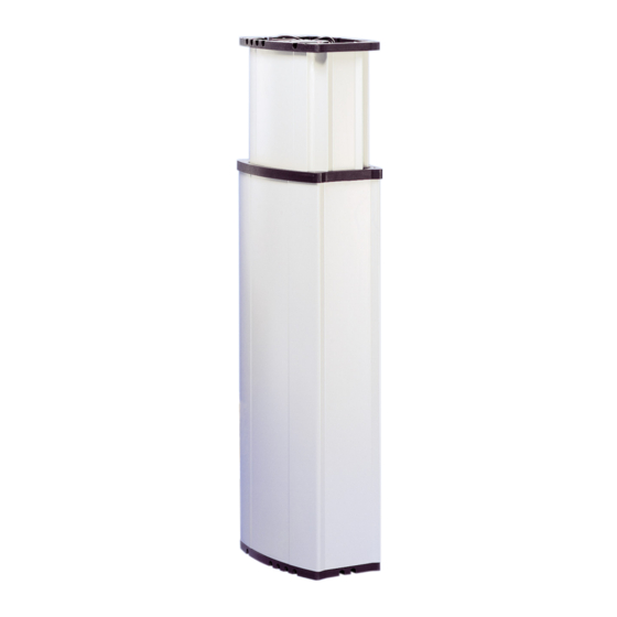
Te l e s m a r t T XG 4.0 Structure and function 4.1 Overview Fig. 2 1. Base plate top 2. Inner tube 3. Rim cover 4. Outer tube 5. Base plate bottom 4.2 Functional description Explanation of terms Stand-alone Actuator with integrated control unit and power supply which is used as an... -
Page 11: Requirements For Third Party Control (Mandatory In Medical Applications)
Control units which are not approved for TXG by Ewellix are treated as third party controls. Where the TXG is equipped with a mains connection (stand- alone and master), the mains voltage is transformed to 24 V • ... -
Page 12: Operating Elements
Cable for electrical The device does not feature its own operating elements The protection can be connected anti-prinching protection operation takes place via a Ewellix operating element at an external (optional) Handswitch (EHE), deskswitch, Ewellix control (⮑ Separate operating manual). Ewellix operating element... -
Page 13: Transport, Packaging And Storage
5 .0 Tr a n s p o r t, p a c k a g i n g a n d s to r a g e 5.0 Transport, packaging and storage 5.1 Safety information for NOTE Report any damage as soon as it has been recognized. the transport Damage claims can only be asserted within the transporter’s applicable complaint period. -
Page 14: Storage
Te l e s m a r t T XG 5.5 Storage Pack the actuator in its original packaging for storage. • Do not store outside. • Dry and dust-free storage. • Keep away from any aggressive media. • Protect from UV radiation. • ... -
Page 15: Installation And First Operation
6 .0 I n s t a l l a ti o n a n d f i r s t o p e r a ti o n 6.0 Installation and first operation 6.1 Installation location Authorized personnel • The installation and first start of operation may only be conducted by qualified personnel. -
Page 16: Installation
Te l e s m a r t T XG 6.3 Installation Any subsequent fastening bores in the aluminium tubes may only be made by Ewellix. The sides of the inner tubes must • Execution by qualified personnel not be scratched, otherwise the tube guide will be damaged. -
Page 17: Connect To The Control Unit
Therefore: • It is recommended to use the Ewellix control unit from the manu- NOTE facturer. The device is connected to the operating element via an external • ... -
Page 18: Connect To Power Supply
Te l e s m a r t T XG 6.6 Connect to power Then fit a cable tie 3 in order to secure the wires. The cable tie should be secured as close to the clamp as possible. supply Each wire (L and N on the electric circuits), is protected by a fuse. -
Page 19: Connect The Second Actuator "Master/Slave" (Optional)
5 .0 Tr a n s p o r t, p a c k a g i n g a n d s to r a g e 6.7 Connect the second 6.8 Strain relief actuator “master/slave” Run all the cables through the ducts in the base plate to the outside. -
Page 20: Operation
Te l e s m a r t T XG 7.0 Operation 7.2.3 Turn off 7.1 Safety NOTE DANGER The device does not feature its own operating elements. The Risk of crashing! operation takes place via a separate operating element While moving onto solid objects, the force of the device may (⮑ Separate operating manual). -
Page 21: Instruction For Use
7.0 O p e r a ti o n Fig. 12 NOTE If no initialisation run is performed with the memory function, the actuator travels in counter-load direction to the terminal position when the “M“ or position keys are actuated. 7.4.2 Instruction for use The actuators can be operated with various operating ele- ments depending on requirements (⮑ 4.6 Accessories, ... -
Page 22: Disengagement In Case Of Emergency
Te l e s m a r t T XG 6. Based on severity of emergency, notify the authorities if Retrieving memory positions • To retrieve a memory position, press the relevant button necessary. 7. Order specialized staff to repair malfunction. on the operating element. Hold the button depressed until the actuators have moved WARNING into position. -
Page 23: Maintenance
8 .0 M a i n te n a n c e 8.0 Maintenance Personnel • The maintenance work described herein can be performed by the operator unless otherwise indicated. • Some maintenance tasks should only be executed by es- pecially trained, qualified personnel, or exclusively by the ... -
Page 24: Maintenance Plan
Te l e s m a r t T XG 8.1 Maintenance plan Maintenance tasks that are required for optimal and trou- ble-free operation are described in the sections below. If increased wear is detected during regular inspections, shorten the required maintenance intervals according to the actual indications of wear. -
Page 25: Inspections And Readings
11 .0 A p p e n d i x 8.2.4 Check of visual condition If an actuator becomes dirty, it should be cleaned immediately in order to prevent the To be performed by qualified personnel accretion of residues! 1. Separate the actuator from the energy supply. 2. -
Page 26: Malfunctions
Te l e s m a r t T XG 9.0 Malfunctions Behavior during malfunctions The following chapter describes potential causes for mal- functions and the work that is necessary to restore In principle: operation. 1. In the event of a malfunction that may present an imme- In the event of frequent malfunctions, shorten the mainte- diate danger to persons or assets, turn off the actuator or ... -
Page 27: Malfunction Table
The actuator cannot be set in motion Exchange device Qualified personnel by any of the above listed measures Internal fuse defective Return device to Ewellix Service Department Qualified personnel Actuator only operates Cut-off mechanism jammed Return device to Ewellix Service Department Qualified personnel in one direction... -
Page 28: Only Txg10 (Slave Or Stand Alone)
Measure static and dynamic load and compare Incorrect load with information on the type label. If the load Qualified personnel capacity is exceeded, replace the device. Identification of defect concerning the Ewellix Defective control unit/operating control unit; if necessary replace defective Qualified personnel element. control, operating element... -
Page 29: Dismantling
• Secure structural components in a way so they would not be able to fall or tip over. • Dispose of metals and plastic components at an appropri- • Contact Ewellix if you have any questions or concerns. ate recycling center. • Sort remaining components based on the respective ma- terial and dispose of according to applicable local occupa- tional health and environmental regulations. -
Page 30: Appendix
Te l e s m a r t T XG 11.0 Appendix Technical Data Sheet PUB IL-07012-EN-October 2019 Telescopic pillar TXG For further technical information please contact Ewellix. - Page 31 11 .0 A p p e n d i x Telesmart telescopic pillar Benefits • Powerful and fast lifting • Aesthetic design Standards • EN/IEC 60601–1 • UL 60601–1 Technical data Unit TXG1 TXG4/5 TXG8/9 Rated push load 1 500 1 500 1 500 Rated pull load...
- Page 32 Te l e s m a r t T XG Dimensional drawing Ø9 Stroke ±2 R 300 4×M6×40 DIN 7 500 included Retracted length ±2 (without mounting plates) Note: mounting plates are not included. To be ordered separately. 4×M6×40 DIN 7 500 included Supporting plate Legend:...
- Page 33 11 .0 A p p e n d i x Performance diagram Bending load diagram Safety factor load conditions Speed-load diagram Speed [mm/s] Load [N] Safety factor (screw buckling) 1 600 1 400 Overload range 1 200 1 000 Ideal load range Under load range 1 000 1 500...
- Page 34 Stroke (S) / Retr. length (L=S+180 or L= S+160 mm) L=S+180 L=S+160 200 mm 300 mm 400 mm 500 mm 600 mm Options written in yellow are only available on demand. Contact Ewellix for more information on minimum quantities and additional costs.
- Page 35 © Ewellix All contents of this publication are the property of Ewellix, and may not be re- produced or given to third parties (even extracts) without permission. Although great care has been taken in the production of this catalog, Ewellix does not take any responsibility for damage or other loss resulting from omissions or ty- pographical errors.
Need help?
Do you have a question about the Telesmart TXG Series and is the answer not in the manual?
Questions and answers