Advertisement
Advertisement
Table of Contents

Summary of Contents for Matrix eBlocks EB066-00-2
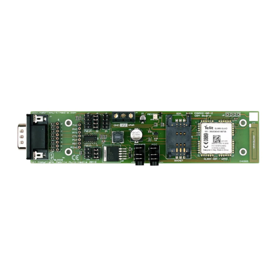
- Page 1 Quad Band GSM/GPRS Board www.matrixmultimedia.com EB066-00-2...
- Page 2 • How to get started with E-blocks - if you are new to at the time of going to press. Matrix Multimedia reserves E-blocks and wish to learn how to use them from the beginning there are resources available to help.
- Page 3 PCB antenna, SIM card • SIM card socket socket, 2.5mm audio jacks for MIC and Headphone audio • Network status LED and signal connection and LED to display the network connection • PCB mounted antenna status. • 5V and 3.3V compatible • E-blocks compatible. Block Diagram Copyright © Matrix Multimedia Ltd.
- Page 4 B (16F877A) Patch Transmit Data (TXD) Bit 5 Bit 6 Patch Receive Data (RXD) Bit 2 Bit 7 Patch Request to send (RTS) Bit 6 Bit 2 Patch Clear to send (CTS) Bit 7 Bit 5 Patch Signal Patch Reset Bit 1 Patch Ring Bit 3 Patch Copyright © Matrix Multimedia Ltd.
- Page 5 When asked press # to send the SMS message. • Connect EB014 (Keypad board) to PORTD of the • Ensure that the AT commands are appearing on Multiprogrammer. the LCD correctly. • Ensure that the GSM EB066 has the following • The test routine has passed if the message is re- jumper configuration: ceived by the remote mobile phone or other GSM device. J5 No Jumper 4-Way Jumper Fitted J7 No Jumper J12 No Jumper J13 4-Way Jumper Fitted Copyright © Matrix Multimedia Ltd.
- Page 6 GSM network the LED will remain constantly lit. The GSM module requires a supply voltage of 3.8V and I/O signal voltage of 2.8V. To allow the module to work Onboard Antenna with 3V3 and 5V systems a voltage shifting circuit has been fitted onto the board. Care must be taken to connect The on-board antenna provides good signal strength even the correct screw terminal to the correct voltage source. in weaker area’s so no external antenna connection has been provided. Copyright © Matrix Multimedia Ltd.
- Page 7 Circuit Diagram Copyright © Matrix Multimedia Ltd.
- Page 8 Matrix Ltd. The Factory 33 Gibbet Street Halifax, HX1 5BA, UK t: +44 (0)1422 252380 e: sales@matrixmultimedia.co.uk www.matrixmultimedia.com EB066-30-2...
Need help?
Do you have a question about the eBlocks EB066-00-2 and is the answer not in the manual?
Questions and answers