Table of Contents

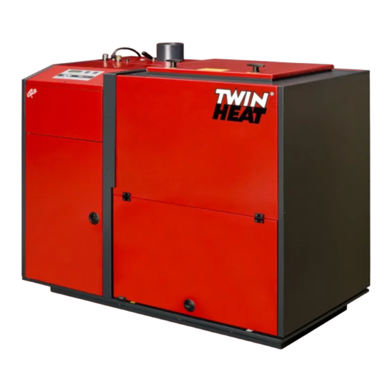
Summary of Contents for Twin Heat CPI 12
- Page 1 Instructions for Installation CPI 12 Version 2.1 - march 2007 Please go trough the instructions, before installing! Nørrevangen 7 • DK-9631 Gedsted • Phone +45 98645222 • Fax. +45 98645244 Mail: twinheat@twinheat.dk • Web: www.twinheat.dk...
- Page 2 Table of contents Lining up the stoker..............page 2 Connection to heating surface .............page 2 Connection to sprinkler system............page 3 Connection to chimney ..............page 3 Electrical connection ..............page 3 Diagram 1 – Connection to heating surface.........page 4 Diagram 2 – Connection to chimney..........page 5 Diagram 3 –...
- Page 3 Lining up the stoker NOTICE: the minimum measures in the “boiler room” must be kept, in order to operate the fuel store as intended. The stoker is delivered on a pallet, ready for installation. The pallet with stoker is to be placed in the boiler room by means of a fork lift truck, ore the like.
- Page 4 Connection to sprinkler system See diagram 1 The sprinkler system at the boiler must be connected to constant water supply G½”, trough a shutoff valve. The connection piece is to be found at the backside base. Make sure that the supply pipe/hose is free of dirt ore the like! When the system is connected and the water supply is open, it has to bee tested.
- Page 5 Diagram 1 - Connection to heating surface TWIN HEAT boiler shunt Closed exp. vessel Open exp. vessel The pipe by the temperature sensor (Tf) is not included! The temperature sensor(Tf) is to be strapped on, to the pipe. Shutoff valve...
- Page 6 Fig. 2: Brick-build chimney Fig. 1: Module chimney (steel) Draught stabilizer Draught stabilizer Elbow Ø133x87° with mudhole Elbow Ø133x87° with mudhole Cpi 12 Cpi 12 The chimney must never be placed directly on the stoker! Cpi 12 DIAGRAM 2 – FEB. 2004...
- Page 7 Diagram 3 – Electrical diagram 400V – 3 phase DIAGRAM 3...
- Page 8 Diagram 3.1 – Electrical diagram 230V – 1 phase DIAGRAM 3.1...
Need help?
Do you have a question about the CPI 12 and is the answer not in the manual?
Questions and answers