
Summary of Contents for KSB Surpress Feu SFE.3
- Page 1 Fire-fighting System Surpress Feu SFE.3 From series 2014w33 Installation/Operating Manual...
- Page 2 Legal information/Copyright Installation/Operating Manual Surpress Feu SFE.3 Original operating manual All rights reserved. The contents provided herein must neither be distributed, copied, reproduced, edited or processed for any other purpose, nor otherwise transmitted, published or made available to a third party without the manufacturer's express written consent.
-
Page 3: Table Of Contents
Dimensions and weights ................15 Terminal wiring diagram ................15 Installation at Site ................16 Safety regulations ................... 16 Installation ...................... 16 Checks to be carried out prior to installation ..........16 Installing the pressure booster system ............17 Surpress Feu SFE.3 3 of 40... - Page 4 General information/Safety regulations ............27 Servicing/inspection ..................28 Trouble-shooting ................30 Related Documents ................32 10.1 List of components ..................32 10.2 Flow diagram ....................33 EC Declaration of Conformity ............35 Certificate of Decontamination ............36 Commissioning Report ...............37 Index ....................38 Surpress Feu SFE.3 4 of 40...
-
Page 5: Glossary
The noise emission to be expected, indicated as environmental and health hazards arising from sound pressure level LpA in dB(A) components in contact with the fluid handled. Surpress Feu SFE.3 5 of 40... -
Page 6: General
The serial/series number uniquely identify the system and serve as identification in all further business processes. In the event of damage, immediately contact your nearest KSB service centre to maintain the right to claim under warranty. Noise characteristics: (⇨ Section 4.6 Page 14) 1.2 Installation of partly completed machinery... -
Page 7: Safety
▪ Only operate pressure booster systems which are in perfect technical condition. ▪ Do not operate partially assembled pressure booster systems. ▪ The pressure booster system must only handle the fluids described in the product literature of the respective design variant. Surpress Feu SFE.3 7 of 40... -
Page 8: Personnel Qualification And Training
▪ The operator shall fit contact guards for hot, cold and moving parts and check that the guards function properly. ▪ Do not remove any contact guards during operation. ▪ Provide the personnel with protective equipment and make sure it is used. Surpress Feu SFE.3 8 of 40... -
Page 9: Safety Instructions For Maintenance, Inspection And Installation Work
Always observe the limits stated in the product literature. The warranty relating to the operating reliability and safety of the system supplied is only valid if the system is used in accordance with its intended use. (⇨ Section 2.3 Page 7) Surpress Feu SFE.3 9 of 40... -
Page 10: Transport/Temporary Storage/Disposal
On transfer of goods, check each packaging unit for damage. In the event of in-transit damage, assess the exact damage, document it and notify KSB or the supplying dealer (as applicable) and the insurer about the damage in writing immediately. -
Page 11: Storage/Preservation
(⇨ Section 12 Page 36) It is imperative to indicate any safety and decontamination measures taken. NOTE If required, a blank certificate of decontamination can be downloaded from the KSB web site at: www.ksb.com/certificate_of_decontamination 3.5 Disposal WARNING... -
Page 12: Description
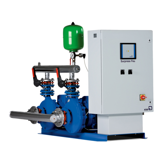
4 Description 4 Description 4.1 General description ▪ Fire-fighting system 4.2 Description Example: Surpress Feu SFE.3 40 - 40 C Table 4: Designation key Code Description Surpress Feu Fire-fighting system SFE.3 With Etabloc GN Etabloc pump size Head in m Type of connection 4.3 Name plate... -
Page 13: Configuration And Function
SFE.3 40-35 SFE.3 40-45 SFE.3 40-50 SFE.3 40-60 SFE.3 32-20 SFE.3 32-30 SFE.3 32-40 SFE.3 32-50 SFE.3 32-60 SFE.3 32-75 SFE.3 40-15 SFE.3 40-25 SFE.3 40-30 SFE.3 40-35 SFE.3 40-45 SFE.3 40-50 SFE.3 40-60 Surpress Feu SFE.3 13 of 40... -
Page 14: Noise Characteristics
▪ Three LEDs signalling the operating status ▪ Motor protection switch per pump ▪ Protective switch for mains and transformer ▪ 1 manual-0-automatic selector switch per pump ("manual" position momentary) Connection types C and V only Surpress Feu SFE.3 14 of 40... -
Page 15: Dimensions And Weights
▪ Contactor per pump ▪ Two volt-free changeover contacts for warning and alert ▪ Connection for lack-of-water monitoring, digital ▪ Service interface for KSB Service Tool 4.8 Dimensions and weights For dimensions and weights refer to the outline drawing of the system. -
Page 16: Installation At Site
NOTE The anti-vibration mounts of the pressure booster system provide adequate insulation against solid-borne noise. Thanks to level-adjustable feet (KSB accessory) the pressure booster system can also be installed in horizontal position on uneven floors. Check the structural requirements. All structural work required must have been prepared in accordance with the dimensions stated in the outline drawing. -
Page 17: Installing The Pressure Booster System
▷ Lay piping with a continuously rising slope (as shown). Suction lift operation Incorrect Correct Fitting the suction line The suction line of each pump must be air-tight, as short as possible and with as few bends as possible. Surpress Feu SFE.3 17 of 40... -
Page 18: Fitting The Dry Running Protection Device
5.8 Electrical connection DANGER Unqualified personnel performing work on the pressure booster system Danger of death from electric shock! ▷ Always have the electrical connections installed by a trained and qualified electrician. Surpress Feu SFE.3 18 of 40... -
Page 19: Notification Of Readiness For Operation
Prior to connecting the package system to the mains, the user must have familiarised himself with the relevant VDE standards. The power supply line must be installed/connected by a duly authorised company only. Surpress Feu SFE.3 19 of 40... -
Page 20: Commissioning/Start-Up/Shutdown
Foreign matter in the piping Damage to the pumps/pressure booster system! ▷ Before commissioning/starting (or even test running) the pressure booster system, make sure that there is no foreign matter in the pressure booster system or piping. Surpress Feu SFE.3 20 of 40... - Page 21 Minor leakage of the mechanical seals during commissioning is normal and will cease after a short period of operation. NOTE If the master switch was switched off at any time during the above procedure, the system will only re-start after a set delay. Surpress Feu SFE.3 21 of 40...
-
Page 22: Switching On The System
As long as the pressure booster system is out of operation, water is supplied directly at p through the pressure booster system. Set the master switch to "0". NOTE Drain the pressure booster system for prolonged shutdown. Surpress Feu SFE.3 22 of 40... -
Page 23: Operating The Pressure Booster System
The control panel comprises a multi-functional button and "traffic light" LEDs on the front as well as terminals on the rear. Fig. 4: Control panel (front): multi-functional button and traffic light LEDs "Traffic light" LEDs Multi-functional button Surpress Feu SFE.3 23 of 40... - Page 24 The "traffic light" LEDs provide information about the pump system's operating status. Table 8: LED description Description Red: One or more than one alert is active Amber: One or more than one warning is active Green: Trouble-free operation Surpress Feu SFE.3 24 of 40...
-
Page 25: Changing Settings
▪ Set the desired start-up pressure by opening the gate valve, referring to the display of the discharge-side pressure gauge. ▪ Press the multi-functional button and switch on the master switch at the same time. ▪ The desired start-up pressure has now been saved. Surpress Feu SFE.3 25 of 40... -
Page 26: Messages
--------- --------- --------- --------- 9 blink(s), 2 sec OFF, 9 blink(s), 2 sec OFF All pumps thermally overloaded ------------------ Continuous Call in customer service. --- --- --- --- ON, briefly OFF, ON, briefly OFF Surpress Feu SFE.3 26 of 40... -
Page 27: Servicing/Maintenance
A regular maintenance schedule will help avoid expensive repairs and contribute to trouble-free, reliable operation of the pressure booster system with a minimum of maintenance expenditure and work. Never use force when dismantling and re-assembling the pressure booster system. Surpress Feu SFE.3 27 of 40... -
Page 28: Servicing/Inspection
Inspection contract For all inspection and servicing work to be carried out at regular intervals we recommend taking out the inspection contract offered by KSB. Contact your Service Partner for details. Checklist for commissioning/inspection and maintenance (. Section 8.2.2 Page 40) 8.2 Servicing/inspection... - Page 29 = 2 bar: pre-charge pressure 2 x 0.8 = 1.6 bar start CAUTION Pre-charge pressure too high Damage to accumulator! ▷ Observe data provided by accumulator manufacturer (see name plate or operating manual of accumulator). Surpress Feu SFE.3 29 of 40...
-
Page 30: Trouble-Shooting
Non-compliance will lead to forfeiture of any and all rights to claims for damages. If problems occur that are not described in the following table, consultation with KSB’s customer service is required. Pumps fail to start in automatic mode or cut out shortly after start-up. Lack of water is indicated. - Page 31 - Inlet tank empty or float switch Check and remedy defect. defective / disconnected The pump pressure must be released before attempting to remedy faults on parts which are subjected to pressure. Disconnect the pump from the power supply! Surpress Feu SFE.3 31 of 40...
-
Page 32: Related Documents
00 106 513 For electric parts refer to the circuit diagram in the Annex. Non-documented parts on request (please indicate serial No. or order No.) NOTE Pump spare parts correspond to Etabloc in standard design. Surpress Feu SFE.3 32 of 40... -
Page 33: Flow Diagram
10 Related Documents 10.2 Flow diagram Scope of supply Fig. 7: Flow diagram for connection type A Fig. 8: Flow diagram for connection type C Surpress Feu SFE.3 33 of 40... - Page 34 69-- 7 71-8 Fig. 10: Options for connection types V and C Part No. Description Part No. Description 69-7 Pressure reducer 82-5 Adapter 71-8 Expansion joint 81-45 Float switch Shut-off valve of fire- fighting system Surpress Feu SFE.3 34 of 40...
-
Page 35: Ec Declaration Of Conformity
67227 Frankenthal (Germany) The manufacturer herewith declares that the product: Surpress Feu SFE.2 KSB order number: ....................▪ is in conformity with the provisions of the following Directives as amended from time to time: – Pump set: Machinery Directive 2006/42/EC –... -
Page 36: Certificate Of Decontamination
We confirm that the above data and information are correct and complete and that dispatch is effected in accordance with the relevant legal provisions....................................Place, date and signature Address Company stamp Required fields Surpress Feu SFE.3 36 of 40... -
Page 37: Commissioning Report
13 Commissioning Report 13 Commissioning Report The KSB pressure booster system specified below was today commissioned by the undersigned authorised KSB customer service engineer who created this report. 1 Pressure booster system details Type series ............................Size ............................Serial number ............................ -
Page 38: Index
Explosion protection 16 Return to supplier 11 Faults Causes and remedies 30 Safety 7 Safety awareness 8 Scope of supply 14 Start-up pressure 26 Installation at site 16 Stop pressure 26 Intended use 7 LEDs 24 Surpress Feu SFE.3 38 of 40... - Page 40 KSB Aktiengesellschaft 67225 Frankenthal • Johann-Klein-Str. 9 • 67227 Frankenthal (Germany) Tel. +49 6233 86-0 • Fax +49 6233 86-3401 www.ksb.com...
Need help?
Do you have a question about the Surpress Feu SFE.3 and is the answer not in the manual?
Questions and answers