
Subscribe to Our Youtube Channel
Related Manuals for Congatec COM Express conga-IT6/COMe

Summary of Contents for Congatec COM Express conga-IT6/COMe
- Page 1 COM Express™ conga-IT6/COMe Detailed description of the congatec COM Express™ Type 6 board based on Mini-ITX form factor User’s Guide Revision 1.0 Copyright © 2018 congatec AG T6COm10.indd 1/45...
- Page 2 Added information about feature connector UARTs to section 5.3.1 "UART Headers" • Changed one power button, one reset button, and a LED to optional in section 7.1 "Power Buttons" and 7.2 "Reset Buttons" • Corrected and added descriptions to section 7.7 "Feature Connector" Copyright © 2018 congatec AG T6COm10.indd 2/45...
- Page 3 In no event shall congatec AG be liable for any incidental, consequential, special, or exemplary damages, whether based on tort, contract or otherwise, arising out of or in connection with this user’s guide or any other information...
- Page 4 Copyright © 2018, congatec AG. All rights reserved. All text, pictures and graphics are protected by copyrights. No copying is permitted without written permission from congatec AG. congatec AG has made every attempt to ensure that the information in this document is accurate yet the information contained within is supplied “as-is”.
- Page 5 (c) arising from course of performance, course of dealing, or usage of trade. congatec AG shall in no event be liable to the end user for collateral or consequential damages of any kind. congatec shall not otherwise be liable for loss, damage or expense directly or indirectly arising from the use of the product or from any other cause.
- Page 6 Technical Support congatec AG technicians and engineers are committed to providing the best possible technical support for our customers so that our products can be easily used and implemented. We request that you first visit our website at www.congatec.com for the latest documentation, utilities and drivers, which have been made available to assist you.
- Page 7 Serial Advanced Technology Attachmen Disc On Module SBM³ Smart Battery Management Secure Digital Serial Peripheral Interface Super I/O Super Input/Output T.B.D To Be Determined UART Universal Asynchronous Receiver/Transmitter Universal Serial Bus Video Graphics Array Copyright © 2018 congatec AG T6COm10.indd 7/45...
-
Page 8: Table Of Contents
LPC Interfaces ................23 Industry Specifications ............. 45 5.3.1 UART Headers ................. 24 5.3.2 SPI 8-Pin Socket ............... 25 GPIO Header ................25 USB 3.0 Type A Ports ............... 26 Gigabit Ethernet Ports ............. 26 Copyright © 2018 congatec AG T6COm10.indd 8/45... - Page 9 X11 Pinout Description ............39 Table 31 X41, X43 Pinout Description ............ 41 Table 32 X40, X42 Pinout Description ............ 41 Table 33 X39 Pinout Description ............42 Table 34 X38 Pinout Description ............43 Copyright © 2018 congatec AG T6COm10.indd 9/45...
-
Page 10: Introduction
The conga-IT6/COMe provides most of the functional requirements for any application. These functions include, but are not limited to a rich complement of contemporary high bandwidth serial interfaces such as PCI Express, Serial ATA, USB 3.0, and Gigabit Ethernet. Copyright © 2018 congatec AG T6COm10.indd... -
Page 11: Optional Accessories
30cm SATA III data cable with straight/right-angled connectors Table 3 Adapters Adapters Part No. Description conga-Thin MITX/eDP to DP adapter 052231 eDP to standard DP evaluation adapter conga-Thin MITX/eDP to HDMI adapter 052232 eDP to standard HDMI evalutiona adapter Copyright © 2018 congatec AG T6COm10.indd 11/45... -
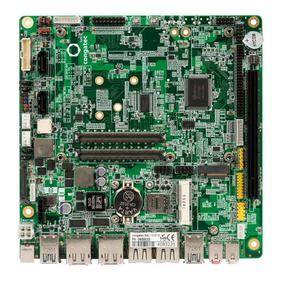
Page 12: Connector Layout
Click on the link to navigate to the area in the document where the component is described. Use the mouse icon in the top left hand corner of the destination page to return to the connector layout picture. Copyright © 2018 congatec AG T6COm10.indd 12/45... -
Page 13: Specifications
1x CR2032 cell battery placed inside a battery holder 1x Beeper Note The module must also support the features for them to function. Refer to the module’s user’s guide for information about supported features. Copyright © 2018 congatec AG T6COm10.indd 13/45... -
Page 14: Mechanical Dimensions
Note The above operating temperatures must be strictly adhered to at all times. The maximum operating temperature refers to any measurable spot on the carrier boards surface. Humidity specifications are for non-condensing conditions. Copyright © 2018 congatec AG T6COm10.indd 14/45... -
Page 15: Connector Description
Ground +12V - 24V Power supply +12V - 24V Ground +12V - 24V Power supply +12V - 24V Connector Type X45: 2x2 pins, 4.2 mm pitch (Molex 87427-0443); Possible Mating Connector: Molex 39-01-2040 Copyright © 2018 congatec AG T6COm10.indd 15/45... -
Page 16: Sbm 3 Connectors
PM_SLP_S3# I2C_CLK PM_SLP_S4# BATLOW# PWRBTN# Connector Type X47: 5x1 pins, 3.00 mm pitch (Molex 43650-0517); Possible Mating Connector: Molex 43645-0500 X48: 8x1 pins, 1.25 mm pitch (Molex 53047-1510); Possible Mating Connector: Molex: 51021-1500 Copyright © 2018 congatec AG T6COm10.indd 16/45... -
Page 17: Cr2032 Cell Battery Holder
X49 : 2x1 pins, 1.25 mm pitch Warning Danger of explosion if battery is incorrectly replaced. Replace only with same or equivalent type recommended by the manufacturer. Dispose of used batteries according to the manufacturer’s instructions. Copyright © 2018 congatec AG T6COm10.indd 17/45... -
Page 18: Subsystems Of Com Express™ Connector Rows A&B
LVDS_B1+ SATA0_RX+ SATA1_RX+ LVDS_A1- LVDS_B1- SATA0_RX- SATA1_RX- LVDS_A2+ LVDS_B2+ GND(FIXED) GND(FIXED) LVDS_A2- LVDS_B2- SATA2_TX+ SATA3_TX+ LVDS_VDD_EN LVDS_B3+ SATA2_TX- SATA3_TX- LVDS_A3+ LVDS_B3- SUS_S5# PWR_OK LVDS_A3- LVDS_BKLT_EN SATA2_RX+ SATA3_RX+ GND(FIXED) GND(FIXED) SATA2_RX- SATA3_RX- LVDS_A_CK+ LVDS_B_CK+ Copyright © 2018 congatec AG T6COm10.indd 18/45... - Page 19 A105 VCC_12V B105 VCC_12V GND(FIXED) GND(FIXED) A106 VCC_12V B106 VCC_12V PCIE_TX5+ PCIE_RX5+ A107 VCC_12V B107 VCC_12V PCIE_TX5- PCIE_RX5- A108 VCC_12V B108 VCC_12V GPI0 GPO1 A109 VCC_12V B109 VCC_12V PCIE_TX4+ PCIE_RX4+ A110 GND(FIXED) B110 GND(FIXED) Copyright © 2018 congatec AG T6COm10.indd 19/45...
-
Page 20: Audio Connectors
X29 Pinout Description Line-OUT Jack Pin Jack Signal Description LINE_L Line-OUT - left channel Ring LINE_R Line-OUT - right channel Ring Sleeve A_GND Analog ground Sleeve Connector Type X29: 3-position, 3.5 mm single audio jack Copyright © 2018 congatec AG T6COm10.indd 20/45... -
Page 21: Stereo Speakers Header
Customized BIOS Surround Out without Line-In SPDIF Out Supported Contact congatec technical support for more information about a customized BIOS. 5.2.4 Digital MIC and S/PDIF Header The conga-IT6/COMe provides a DMIC header (X26). Alternatively, it can be used as S/PDIF output. -
Page 22: Front Panel Audio Header
Surround Out with Line-In DMIC Customized BIOS Surround Out without Line-In SPDIF Out Supported Contact congatec technical support for more information about a customized BIOS. 5.2.5 Front Panel Audio Header The conga-IT6/COMe provides a front panel audio header (X25). Table 14... -
Page 23: Surround Sound Header
DMIC Customized BIOS Surround Out without Line-In SPDIF Out Supported Contact congatec technical support for more information about a customized BIOS. LPC Interfaces The interfaces in the following subsections are routed from an LPC Super I/O controller (Winbond W83627UHG). Note The module must also support the interfaces for them to function. -
Page 24: Uart Headers
COM0 (X34) COM1 (X35) COM2 (X36) COM3 (X37) Standard BIOS RS-232 RS-232 RS-232 RS-232 RS-232 RS-232 Customized BIOS RS-422 RS-422 RS-422 RS-422 RS-485 RS-485 RS-485 RS-485 Contact congatec technical support for more information about a customized BIOS. Copyright © 2018 congatec AG T6COm10.indd 24/45... -
Page 25: Spi 8-Pin Socket
Table 17 X44 Pinout Description X44 Signals X44 Signals I2C_IO_00 I2C_IO_10 I2C_IO_01 I2C_IO_11 I2C_IO_02 I2C_IO_12 I2C_IO_03 I2C_IO_13 I2C_IO_04 I2C_IO_14 I2C_IO_05 I2C_IO_15 I2C_IO_06 I2C_IO_16 I2C_IO_07 I2C_IO_17 VCC5V_SBY Connector Type X44: 9x2 pins, 2.54 mm pitch Copyright © 2018 congatec AG T6COm10.indd 25/45... -
Page 26: Usb 3.0 Type A Ports
No activity Green 100 Mbps link speed Blinking Link established, activity detected Orange 1000 Mbps link speed Connector Type X5, X6: RJ45 port with Gigabit 12 core magnetic and two LEDs (Green, Green/Orange) Copyright © 2018 congatec AG T6COm10.indd 26/45... -
Page 27: Sata Connectors
The conga-IT6/COMe provides two SATA 6Gb/s ports (X14 and X15). You can enable SATADOM on SATA0 port (X14) with jumper X50. You can enable SATADOM on SATA1 port (X15) with jumper X51. SATA1 (X15) SATA0 (X14) Serial ATA Channel 0 Serial ATA Channel 1 Copyright © 2018 congatec AG T6COm10.indd 27/45... -
Page 28: Table 20 Jumper X50, X51 Settings
Do not connect a SATA device to a connector set to SATADOM. Otherwise, this will cause a short, possibly damaging the hardware. Connector Type X14, X15: SATA port X50, X51: 3x1 pins, 2.54 mm pitch Copyright © 2018 congatec AG T6COm10.indd 28/45... -
Page 29: Lvds Header
LVDS_CLK-P LVDS_CLK-N LVDS_CLK-N LVDS_I2C_CLK LVDS_I2C_DAT LVDS_PWR LVDS_PWR LVDS_PWR N.C. LVDS_VDD_EN Note You can use either LVDS or eDP. Connector Type X53: 40 pins, 1.00 mm pitch (Molex 501190-4017); Possible Mating Connector: Molex 501189-4010 Copyright © 2018 congatec AG T6COm10.indd 29/45... -
Page 30: Edp Connector
BKLT_PWR VCC_LCD BKLT_PWR VCC_LCD BKLT_PWR VCC_LCD Note You can use either LVDS or eDP. Connector Type X20: 40 pins, 0.5 mm pitch (ACES 50203-040); Possible Mating Connector: ACES 50204-40-0500LI Copyright © 2018 congatec AG T6COm10.indd 30/45... -
Page 31: Flat Panel Backlight Header
You can set the panel voltage with jumper X22 and the backlight voltage with jumper X20. Table 24 X22 Pinout Description Pin 2 Jumper Position Panel Voltage Pin 6 +3.3V +12V No Pin No Pin Default Settings: Pin 3 Pins 2 and 4 Copyright © 2018 congatec AG T6COm10.indd 31/45... -
Page 32: Vga Header
The conga-IT6/COMe provides a VGA header (X31). The signals are routed from a DP to VGA adapter (NXP PTN3392BS). Optionally, the signals can be routed from the module. Table 26 X31 Pinout Description Signal VGA_CLK_B VGA_DAT_B VGA_HS_B VGA_VS_B VGA_BLU_B VGA_GRN_B VGA_RED_B Connector Type X31: 8x1 pins, 2.00 mm pitch (JS 1125-08) Copyright © 2018 congatec AG T6COm10.indd 32/45... -
Page 33: Microsd Card Slot
The conga-IT6/COMe provides a microSD card slot (X17) at the bottom of the board. You can enable it by setting DIP switch 2 to OFF. Optionally, a full-size SD card slot (X54) can be placed instead. Connector Type X17: microSD card slot X54: Full-size SD card slot Copyright © 2018 congatec AG T6COm10.indd 33/45... -
Page 34: Subsystems Of Com Express™ Connector Rows C&D
RSVD RSVD PCIE_RX6+ PCIE_TX6+ PEG_RX7+ PEG_TX7+ PCIE_RX6- PCIE_TX6- PEG_RX7- PEG_TX7- GND(FIXED) GND(FIXED) PCIE_RX7+ PCIE_TX7+ RSVD RSVD PCIE_RX7- PCIE_TX7- PEG_RX8+ PEG_TX8+ DDI1_HPD RSVD PEG_RX8- PEG_TX8- DDI1_PAIR4 + RSVD GND(FIXED) GND(FIXED) DDI1_PAIR4- DDI1_PAIR0+ PEG_RX9+ PEG_TX9+ Copyright © 2018 congatec AG T6COm10.indd 34/45... - Page 35 VCC_12V D105 VCC_12V GND(FIXED) GND(FIXED) C106 VCC_12V D106 VCC_12V PEG_RX0+ PEG_TX0+ C107 VCC_12V D107 VCC_12V PEG_RX0- PEG_TX0- C108 VCC_12V D108 VCC_12V TYPE0# PEG_LANE_RV# C109 VCC_12V D109 VCC_12V PEG_RX1+ PEG_TX1+ C110 GND(FIXED) D110 GND(FIXED) Copyright © 2018 congatec AG T6COm10.indd 35/45...
-
Page 36: Dp++ And Hdmi Ports
Gigabit Ethernet M.2 Key B 2242 / 3042 Slot PCI Express ® Mini Card Slot (Top) PCI Express ® Graphics (PEG) Card Slot Note Interfaces with overlapping PCI Express lanes are mutually exclusive. ® Copyright © 2018 congatec AG T6COm10.indd 36/45... -
Page 37: Pci Express ® Graphics (Peg) Card Slot
The conga-IT6/COMe provides an M.2 Key B 3042 / 2242 card slot (X10). Table 29 X10 Pinout Description Pin Signal Pin Signal CONFIG_3 +3.3V +3.3V FULL_CARD_PWROFF# USB_D+ W_DISABLE_1# USB_D- LED1 (optional) CONFIG_0 WoWWAN# W_DISABLE_2# Copyright © 2018 congatec AG T6COm10.indd 37/45... - Page 38 UIM_PWR PET1+ DEVSLP GNSS_SCL PER0-/SATA_B+ GNSS_SDA PER0+/SATA_B- GNSS_IRQ PET0-/SATA_A- PET0+/SATA_A+ RESET# CLKREQ# REFCLK- PEWAKE# REFCLK+ RESET# SUSCLK CONFIG_1 +3.3V +3.3V +3.3V CONFIG_2 Connector Type X10: M.2 Key B 3042 / 2242 card slot Copyright © 2018 congatec AG T6COm10.indd 38/45...
-
Page 39: Pci Express ® Mini Card Slots
PCI Express Mini card slot (X12) instead. ® Table 30 X11 Pinout Description Signal Description Power Reset Clock Not available Ground Programming voltage input Data Not available Connector Type X11: Micro-SIM card slot Copyright © 2018 congatec AG T6COm10.indd 39/45... -
Page 40: Additional Features
COM Express™ module’s SYS_RESET# signal. Beeper The conga-IT6/COMe provides a beeper (M27). It provides audible error code (beep code) information during POST. The beeper is connected to the COM Express™ module’s SPEAKER signal. Copyright © 2018 congatec AG T6COm10.indd 40/45... -
Page 41: Ground Potential Test Points
X40 , X42 Jumper X40, X42 Configuration 1 - 2 FAN +12VDC (default) 2 - 3 FAN +5VDC Connector Type X41, X43: 4x1 pins, 2.54 mm pitch X40, X42: 3x1 pins, 2.54 mm pitch Copyright © 2018 congatec AG T6COm10.indd 41/45... -
Page 42: Front Panel Header
Hard disk activity LED (cathode) FP_LED- Power LED (alternate color) Ground PWRBTN# Power Button SYS_RST# Reset Button Ground +V5S +5V power supply (500mA power budget) No pin Connector Type X39: 5x2 pins, 2.54 mm pitch Copyright © 2018 congatec AG T6COm10.indd 42/45... -
Page 43: Feature Connector
SPI_SO SPI serial output BIOS_DISABLE# Determine the boot device. SPI_CLK SPI flash clock input SPI_MOSI SPI flash data input +V5_SBY 5V standby supply Power Ground Connector Type X38: 22x2 pins, 2.54 mm pitch Copyright © 2018 congatec AG T6COm10.indd 43/45... -
Page 44: Mechanical Dimensions
Mechanical Dimensions M33 M35 M34 D30 D31 163.8 Copyright © 2018 congatec AG T6COm10.indd 44/45... -
Page 45: Industry Specifications
LVDS Owner's Manual http://www.ti.com/lit/ml/snla187/snla187.pdf Extended Display Identification Data Standard (EDID™) http://www.vesa.org Enhanced Display Data Channel Specification (DDC) http://www.vesa.org IEEE standard 802.3ab 1000BASE T Ethernet http://www.ieee.org/portal/site Advanced Configuration and Power Interface Specification http://www.acpi.info/ Copyright © 2018 congatec AG T6COm10.indd 45/45...
Need help?
Do you have a question about the COM Express conga-IT6/COMe and is the answer not in the manual?
Questions and answers