
Related Manuals for ENDEVCO 4418

Summary of Contents for ENDEVCO 4418
- Page 1 Instruction Manual 4418 Bridge Signal Conditioner DOCUMENT EDVIM4418 REVISION B Page 1 of 14...
- Page 2 CFR 47, Class A Code of Federal Regulations: Pt 15, Subpart B The 4418 has been tested as an Unintentional radiator (sub part B) and as a Class A product. RADIO AND TELEVISION INTERFERENCE NOTE: This equipment has been tested and found to comply with the limits for a Class A digital device, pursuant to Part 15 of the FCC rules.
-
Page 3: Table Of Contents
Table of Contents Page Product Description Detailed Description 2.1 Input 2.1.1 Connection 2.1.2 Status 2.2 Output 2.2.1 Connection 2.2.2 Gain 2.2.3 Filter 2.3 Power 2.3.1 Turn On 2.3.2 Low Battery Indicator 2.3.3 Battery Charge Indicator Operation Transducer Connection Output Connection Gain Setting Filter Selection ZMO Adjustment... -
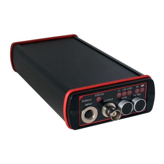
Page 4: Product Description
1. Product Description The Model 4418 Bridge Signal Conditioner is a portable/desk top low-noise Signal Conditioner for use with Bridge and Variable Capacitance type transducers. The unit provides the excitation supply to the transducer, signal amplification and filtering. Signal amplification (gain) is selectable as x1, x10 or x100 and the fixed frequency cut-off filter is selectable as IN or OUT. -
Page 5: Filter
Operation It is recommended that the 4418 be placed on charge before using for the first time. Note: Ensure the Conditioner is turned off before making any connecting to the 4418. Once connections have been made, the unit can be turned on with the switch located on the rear panel. -
Page 6: Gain Setting
*Pin 3 is connected to output signal ground. Fig 3. Pin Connections - as viewed from the front of the 4418 or the rear (wire side) of the mating input plug. Output Connection Measuring Instrumentation, e.g. data acquisition, data logger etc. should be connected to the output socket using coaxial cables. -
Page 7: Battery Charging
therefore, recommended that the zero measured offset be adjusted first on the x1 and/or x10 to set the control in the right region. Battery Charging Ensure that both the Charger and Conditioner are turned OFF before connecting. Plug the Charger connector into the socket on the rear panel of the Conditioner. - Page 8 Fig 4. Simplified Block Diagram 4. Maintenance, Calibration and Repair If the unit is suspected of not working or malfunctioning it can be checked by use of the following circuit. This circuit should also be used when performing a calibration of the unit. Note: To verify the LF response of the signal conditioner it will be necessary to increase the value of the capacitor.
- Page 9 Set the signal generator (AC) for 70.7 mVpk (50 mV rms) at a frequency of 100Hz. Turn on the 4418 and select a gain of x1. Allow 5 minutes to stabilize. 4.1.3 Check Procedure Connect the DMM and Oscilloscope to the output of the 4418.
- Page 10 This page is Left intentionally blank DOCUMENT EDVIM4418 REVISION B Page 10 of 14...
- Page 11 TYPICAL FREQUENCY RESPONSE CURVES: DOCUMENT EDVIM4418 REVISION B Page 11 of 14...
- Page 12 DOCUMENT EDVIM4418 REVISION B Page 12 of 14...
- Page 13 DOCUMENT EDVIM4418 REVISION B Page 13 of 14...
- Page 14 DOCUMENT EDVIM4418 REVISION B Page 14 of 14...
Need help?
Do you have a question about the 4418 and is the answer not in the manual?
Questions and answers