Table of Contents
Advertisement
Quick Links
Advertisement
Chapters
Table of Contents

Summary of Contents for Baur SSG 500
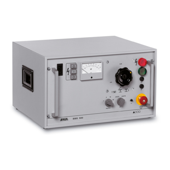
- Page 1 Surge Voltage Generator SSG 500 Ident. Nr. 822-016 02/2011 e-mail: headoffice@baur.at Tel +43 / 55 22 / 49 41-0 BAUR Prüf- und Messtechnik GmbH internet: http://www.baur.at Fax +43 / 55 22 / 49 4 13 Raiffeisenstrasse 8, A-6832 Sulz / Austria...
- Page 3 This manual contains all information necessary for the correct Preface handling and use of the surge voltage generator SSG 500. Before using the surge voltage generator, please read carfully this Operating Instruction: If you have any question, please contact directly: BAUR Prüf- und Messtechnik GmbH, Raiffeisenstrasse 8...
- Page 4 Sicherheitshinweise, Garantie Safety Precautions, Continued It is imperative to every person who is involved with the installation, start-up, operation and maintenance of the SSG 500 to have read and understood the complete Operating Instruction. Please read now and avoid damage and injury later!
-
Page 5: Table Of Contents
Contents Contents 1. Product Information ................. 1-1 Overview ............1-1 Design and function ........1-2 Display and operating elements...... 1-3 Technical data ..........1-5 2. Packing and Delivery ............... 2-1 Damage during transport ........ 2-1 3. Setting into operation ..............3-1 Overview ............ - Page 6 Notes Notes...
-
Page 7: Product Information
1. Product Information 1. Product Information Overview In this section you will find all necessary product information for the Surge Voltage Generator SSG 500. This section covers the following subjects: Subject Page Design and function Display and operating elements Technical data... -
Page 8: Design And Function
3 / 6 / 12kV using the reduction switch (13) 56% of the surge energy are available. The Surge Voltage Generator SSG 500 is designed in such a way Function that it generates pulse-shaped voltages with a steep edge, which should start to break down the cable fault. -
Page 9: Display And Operating Elements
1. Product Information Display and operating elementes Front panel Mains switch as overload protection switch with thermal release Pushbutton switch „Ready to switch on“ ( Pushbutton switch „H.V. On“ ( I ) with warning lamp for high voltage clearance. The indicator lamp serves as feedback for the operating state „IN OPERATION“... - Page 10 1. Product Information Backplate Connection socket for external EMERGENCY OFF unit with jumper plug Connection for mains to SA 32 Connection for mains Terminal for connection of protective earth lead Type plate High voltage connecting lead...
-
Page 11: Technical Data
1. Product Information Technical data SSG 500 unit Mains voltage see type plate Mains frequency 45 to 60 Max. power consumption (at short ciruit condition) 1.500 Max. output voltage Max. surge energy Accuracy of kV-meter Dimensions of housing (W x H x D) - Page 12 1. Product Information Notes...
-
Page 13: Damage During Transport
If damage is discovered during unpacking, contact the responsible transportation company immediately. Request a written loss assessment and make them responsible for the damage! We also refer to the “General Terms of Sale and Delivery„ of: BAUR Prüf- und Messtechnik GmbH, A-6832 Sulz / Austria... - Page 14 2. Packing and Shipping Notes...
-
Page 15: Overview
3. Placing into operation 3. Placing into operation Overview In this section you will find all necessary information to put the Surge Voltage Generator SSG 500 into operation. This section describes the following subjects: Subject Page Modes Connection of instrument... - Page 16 Automatic impulse triggering is primarily used for pin-pointing a Automatic impulse triggering cable fault. The SSG 500 is equipped with a timer coupled to the mains frequency which allows automatic impulse triggering with impulse frequencies of 10/min and 20/min. The regularity of the subsequent impulses serves to better differentiate between the signals of the fault location and interferences.
- Page 17 3. Placing into operation The Surge Voltage Generator can be put into D.C. operation via the DC Operation mode selector switch (14). Turn mode selector switch (14) to the fully left position =. The spark gap will be permanently closed and therefore connects the high voltage output directly with the surge capacitor.
-
Page 18: Connection Of Instrument
3. Placing into operation Connection of instrument Observe correct position of connection terminals! (also see Note on page 3-5) Connection to a single-phase shielded cable Connection of a three-phase shielded cable Connection to a three-phase unshielded cable with neutral Rear view of device - Protective ground connection 2. - Page 19 3. Placing into operation Preparing test object • Isolate the test object • Lock against reconnection • Make sure that zero voltage condition exists. • Insulate nearby items which are under voltage • It must be assured that nearby items of the station or cable system under voltage do not result in breakovers or breakdowns, due to applying surge or D.C.
-
Page 20: Connection Of Mains
3. Placing into operation Estabilshing H.V. connection • Connect strand of the high voltage connecting lead with the fault afflicted strand of the test object. It is very important that all connections are of low resistance as possible. Bad connections can lead to weldings or contact wear. •... -
Page 21: Switch On
3. Placing into operation Select 3 / 6 / 12 kV (56%) or 4 / 8 / 16 kV (100% surge energy) Switch on using the reduction switch. Set range selector switch (6) to the desired range 3 / 6 / 12 kV or 4 / 8 / 16 kV. -
Page 22: Switch Off
Live parts must be discharged, earthed and shorted. The Surge Voltage Generator SSG 500 features an internal discharge unit, but not an internal earthing unit. Before cancelling the safety precautions, it is essential that all live parts are discharged, earthed and shorted, because they could have residual charges, caused by possible interruptions. -
Page 23: Emergency Switching Off
3. Placing into operation Press EMERGENCY OFF pushbutton switch (11). EMERGENCY OFF The instrument returns to the operating condition „READY FOR OPERATION“. The high voltage transformer will be isolated from the supply voltage. the indicator lamp „In Operation“ of pushbutton switch (3) is out the red indicator lamp (7) is out the green indicator lamp (8) is illuminated... - Page 24 3. Placing into operation Notes 3-10...
-
Page 25: Overview
4. Servicing / Maintenance 4. Servicing / Maintenance Overview In this section you will find all necessary information for servicing / maintenance of the Surge Voltage Generator SSG 500. This section describes the following subjects: Subject Page Safety precautions Fuses... - Page 26 - has adequate knowledge for maintaining and servicing the SSG 500 - has been authorized explicitly by BAUR to open the SSG 500 and perform changes on the instrument. Fuses The two fuses F3 and F4 on the front panel of the surge voltage...
-
Page 27: Checking The Discharge Unit
4. Servicing / Maintenance Description Value Dimension Ident.No. Remarks F1, F2 0,16 AT Ø 5 x 20 mm 563-005 Mains transformer, primary F3, F4 internal 2 AF Ø 5 x 20 mm 563-020 + 12V control F3, F4 external 3,15 AT Ø... - Page 28 4. Servicing / Maintenance Notes...
-
Page 29: Options, Accessories And Ordering Information
5. Options, Accessories and Ordering Information Overview In this section you will find all neccessary information about options, accessories and ordering information for the Surge V oltage Gene- rator SSG 500. This section describes the following subjects: Subject Page Options... -
Page 30: Options
5. Options, Accessories and Ordering Information Options The primary application of the Intercom SA 32 is as „aid“ for pre- Intercom SA 32 locating of cable faults. It allows locating of high-resistance faults utilizing the secondary impulse method (SIM). This allows for transformation of high-resistance faults into low- resistance faults. -
Page 31: Accessories
EMERGENCY OFF unit is plugged in the instrument will not be operational. Ordering information Mains voltage 220-230V 110-120V*) 240V Surge voltage generator SSG 500 with accessories 414-005 414-105 414-205 Surge voltage generator SSG 500 without accessories 470-283 470-282 470-284 Items included... - Page 32 5. Options, Accessories and Ordering Information Notes...
Need help?
Do you have a question about the SSG 500 and is the answer not in the manual?
Questions and answers