Table of Contents
Advertisement
Available languages
Available languages
Quick Links
Advertisement
Chapters
Table of Contents

Summary of Contents for KRS TECH AQUA DUO Series
- Page 1 KRS TECH AQUA DUO...
-
Page 2: Table Of Contents
DOKUMENTACJA TECHNICZNO-RUCHOWA kotłów wodnych centralnego ogrzewania typu KRS TECH AQUA DUO z automatycznym układem podawania paliwa SPIS TREŚCI 1. WSTĘP ..............................................2. PRZEZNACZENIE KOTŁA ......................................3. OPIS BUDOWY KOTŁA ......................................4. PALIWO ..............................................4.1. Paliwo podstawowe ....................................4.2. Paliwo zastępcze ..................................... -
Page 4: Wstęp
Dokładne zapoznanie się z instrukcją obsługi oraz stosowanie się do wskazówek w niej zawartych pozwoli na bezpieczną, prawidłową i długoletnią eksploatację kotłów c.o. typu KRS TECH AQUA DUO. Każdy posiadacz przed przystąpieniem do zainstalowania i eksploatacji kotła powinien dokładnie zapoznać się z instrukcją obsługi. Dokładne zapoznanie się z dokumentacją jest niezbędne dla zapewnienia prawidłowego i bezpiecznego ich użytkowania. -
Page 5: Przeznaczenie Kotła
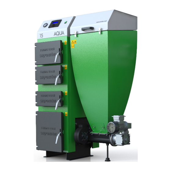
2. PRZEZNACZENIE KOTŁA Kotły typu KRS TECH AQUA DUO z palnikiem retortowym żeliwny,, przeznaczone są do wodnych instalacji centralnego ogrzewania systemu otwartego, z grawitacyjnym jak i wymuszonym obiegiem wody. Instalacja musi być zabezpieczona zgodnie z obecnie obowiązującymi, szczegółowymi przepisami krajowymi. - Page 6 Rys. 1 Wymiary i opis kotła. 1 – termometr z manometrem 14 – wyczystka czopucha 2 – sterownik 15 – króciec wylotu wody ciepłej 3 – włącznik główny 16 –zawór bezpieczeństwa (strażak). 4 – drzwi wyczystne 17 – panel gniazd urządzeń zewnętrznych 5 –...
- Page 7 Tab. 1 Wymiary kotła Typ kotła Parametr (mm) AQUA 15 AQUA 20 AQUA 25 1380 1385 1380 1095 1095 1095 ∅ 158 ∅ 178 ∅ 178 1070 1150 1150 1510 1535 1535 1175 1095 1095 Tab. 2 Parametry kotła l.p. Wyszczególnienie Jednostki Dane 1 Nominalna moc kotła...
-
Page 8: Paliwo
Podane wielkości powierzchni grzewczych są orientacyjnymi wielkościami doboru kotła. Każdy użytkownik powinien dobrać kocioł C.O. pod własne potrzeby budynku, uwzględniając: rodzaj instalacji, współczynnik przenikania ścian budynku oraz docieplenie. Producent nie ponosi odpowiedzialności za źle dobrany kocioł do budynku. Sugeruje się, aby do dobrze ocieplonego budynku z nowoczesną... -
Page 9: Ustawienie Kotła
- drzwi wejściowe do kotłowni powinny otwierać się na zewnątrz pomieszczenia i muszą być wykonane z materiałów niepalnych, - kotłownia powinna mieć wentylację nawiewną w postaci kanału o przekroju nie mniejszym niż 50% przekroju komina, lecz nie mniej niż 21 x 21 cm, z wylotem w tylnej części kotłowni (brak wentylacji nawiewnej lub jej niedrożność... -
Page 10: Podłączenie Kotła Do Komina
5.3. PODŁĄCZENIE KOTŁA DO KOMINA Sposób wykonania przewodu kominowego oraz podłączenia do niego kotła powinien być zgodny z wymogami obecnie obowiązujących szczegółowych przepisów kraju przeznaczenia (np. Rozporządzenie Ministra Infrastruktury z dnia 12.04.2002 Dz.U.nr 75). Kocioł należy podłączyć bezpośrednio do komina za pomocą przyłącza dymowego wykonanego w postaci rury stalowej (o wytrzymałości temp. -
Page 11: Podłączenie Kotła Do Instalacji Grzewczej
instrukcji należy przechowywać wraz z gwarancją kotła. W przypadku, gdy nie ma możliwości zapewnienia zalecanych parametrów komina, a występują problemy z ciągiem kominowym, co objawia się nieprawidłową pracą kotła, można zastosować wentylator wyciągowy spalin lub nasadę kominową z wbudowanym wentylatorem, która wspomaga i stabilizuje ciąg. Istotne jest, aby komin zaczynał... - Page 12 Brak izolacji w miejscach gdzie są spadki temperatury poniżej 0°C oraz usytuowanie naczynia wzbiorczego niezgodnie z PN-91/B-02413 może być podstawą do nie uznania reklamacji. Kotły typu KRS TECH AQUA DUO mogą pracować zarówno z grawitacyjnym jak i wymuszonym obiegiem wody. Jeżeli w instalacji zastosowana jest pompa obiegowa na rurze zasilającej/powrotnej powinien zostać...
-
Page 13: Instalacja Elektryczna
5.5. INSTALACJA ELEKTRYCZNA Sterowanie przeznaczone jest do zasilania napięciem 230V, 50Hz. Instalacja powinna być wykonana przez osobę posiadającą odpowiednie uprawnienia. W przypadku stwierdzenia jakichkolwiek uszkodzeń przewodów elektrycznych – nie wolno dokonywać podłączeń kotła, gdyż grozi to porażeniem prądem. Instalacja powinna być wykonana z przewodem ochronnym. Kocioł musi być prawidłowo uziemiony. -
Page 14: Sterownik Elektroniczny
W przypadku stosowania paliwa o zbyt dużych ziarnach, lub zawierającego dużo pyłu, istnieje prawdopodobieństwo zerwania śruby zabezpieczającej przed przeciążeniem na motoreduktorze, możliwe jest również uszkodzenie motoreduktora. W takiej sytuacji następuje utrata gwarancji. Awarię związaną z zerwaniem śruby zabezpieczającej można łatwo naprawić samodzielnie. Wystarczy wyjąć pozostałości uszkodzonej i wstawić nową. Wymiana zawleczki nie powoduje utraty gwarancji na wyrób. -
Page 15: Wytyczne Obsługi L Eksploatacji
6. WYTYCZNE OBSŁUGI l EKSPLOATACJI 6.1. NAPEŁNIANIE WODĄ Napełnianie kotła i całej instalacji wodą powinno odbywać się przez zawór spustowy kotła. Czynności te należy wykonać tak aby nie zapowietrzyć instalacji. O całkowitym napełnieniu instalacji wodą świadczy wypływ wody z rury przelewowej. Sprawdzenie należy wykonać przez okres kilku sekund aby upewnić się, że woda spływa z naczynia wzbiorczego. -
Page 16: Tryb Pracy Półautomatycznej
6.2.2. TRYB PRACY PÓŁAUTOMATYCZNEJ Rozpalanie paliwa w kotle należy rozpocząć po uprzednim upewnieniu się , że instalacja grzewcza napełniona jest wodą, oraz czy nie nastąpiło jej zamarznięcie. Należy również sprawdzić czystość dysz powietrznych w palniku (rys.1 poz. 20 i 21). Przed rozpaleniem należy między ruszta wodne ułożyć załączone do kotła ruszta żeliwne sztabowe. Drzwiczki popielnika powinny być... -
Page 17: Czyszczenie Kotła
przyspawanych kątownikach. Należy pamiętać, aby wyjąć je w chwili przejścia na pracę automatyczną kotła. Należy pamiętać aby zasyp paliwem był niższy od drzwiczek zasypowych, nie należy również wsypywać paliwa na klin będący wymiennikiem kotła, gdyż może to znacznie ograniczyć ciąg. 6.3. -
Page 18: W Celu Utrzymania Kotła W Należytym Stanie Technicznym Należy
rozgrzany, gdyż może to spowodować awarię kotła, - wszystkie usterki kotła niezwłocznie usuwać, - stosować paliwa zalecane przez Producenta, - nie ingerować samemu w elementy elektroniki, - zaleca się wykonywanie prac obsługowych kotła w rękawicach ochronnych, - czyszczenie kotła z sadzy i popiołu należy wykonywać podczas postoju kotła, - podczas czyszczenia kotła należy dobrze przewietrzyć... -
Page 19: Przed Wezwaniem Serwisu
9. PRZED WEZWANIEM SERWISU Zanim Państwo wezwiecie serwis, prosimy zapoznać się z poniższymi objawami zakłóceń pracy kotła niezależnych od producenta: 9.1. Kocioł nie osiąga zadanej temperatury (nominalnej mocy cieplnej) - niedostateczny ciąg kominowy - należy sprawdzić i usunąć ewentualne nieszczelności komina, czopucha, drzwiczek kotła lub otworów wyczystnych, oczyścić... -
Page 20: Instrukcje
10. Instrukcje 10.1. Instrukcja regulacji siły docisku drzwiczek W celu regulacji docisku (szczelności) należy poluzować nakrętki (1) i (2), następnie nakrętkę (2) wkręcić obracając w prawo o jeden obrót i zakontraktować nakrętką (1). Sprawdzić, czy drzwiczki się dobrze się zamykają. Jeśli nie, należy tą czynność powtarzać, aż do uzyskania wymaganego docisku. -
Page 21: Instrukcja Zmiany Kierunku Otwierania Drzwiczek
10.3. Instrukcja zmiany kierunku otwierania drzwiczek Przed przystąpieniem do tej operacji trzeba zdjąć drzwiczki ( patrz „Instrukcja zdejmowania lub wymiany drzwiczek”) Rys. 8 Instrukcja zdejmowania lub wymiany drzwiczek – 1 3. Kątownik zamykania drzwiczek 4. DIN 603 M8 x 16 5. - Page 22 Rys. 10 Instrukcja zdejmowania lub wymiany drzwiczek – 3 7. DIN 933 M8 x 20 8. DIN 126 M8 9. Blacha izolacji drzwiczek 10. Izolacja drzwiczek 11. DIN 1472 Ø8 x 30 12. Rączka zamykania drzwiczek Rys. 11 Instrukcja zdejmowania lub wymiany drzwiczek - 4 2.
-
Page 23: Wykaz Elementów Wchodzących W Skład Drzwiczek
10.4. Wykaz elementów wchodzących w skład drzwiczek Tab. 3 Wykaz elementów wchodzących w skład drzwiczek żeliwnych. Pozycja Norma Rozmiar Sztuk / kp Opis Nakrętka sześciokątna niska DIN 439 DIN 439 Nakrętka sześciokątna niska ---------------- -------------------- Kątownik zamykania drzwiczek DIN 603 M8 x 16 Śruba zamkowa (ławkowa) DIN 934... - Page 24 Rys. 12 Instrukcja montażu zbiornika z wodą do zaworu bezpieczeństwa (strażaka). 1 – Zawór 2 – Czujnik zaworu 3 – Tuleja mocująca czujnik 4 – Przycisk zwalniający przepływ wody 5 – Spirala czujnika temperatury Wskazane jest sprawdzenie poprawności działania zaworu przed każdym sezonem. Dokonuje się tego poprzez naciśnięcie czerwonego guzika na zaworze i sprawdzenie, czy przepływa woda.
-
Page 25: Gwarancja
11. GWARANCJA WARUNKI GWARANCJI: Gwarancja obowiązuje na terytorium RP. 1. Producent gwarantuje sprawne działanie kotła centralnego ogrzewania, co potwierdza się pieczęcią zakładu i punktu handlowego na okres: a) 5 lat od daty produkcji na szczelność korpusu wodnego kotła. b) 2 lat od daty zakupu na trwałość pozostałych elementów i sprawne działanie kotła. c) 6 miesięcy na elementy żeliwne kotła: deflektor, ruszta żeliwne i ruszta sztabkowe. - Page 26 Wykaz części zamiennych kotła TECH ECO DUO Nazwa Sterownik kotła Czujnik temperatury kotła Czujnik STB kotła Czujnik STB palnika Wentylator kotła Motoreduktor podajnika (kpl. Silnik + przekładnia ) Kratka żeliwna Ruszto żeliwne Blacha ze sworzniem drzwiczek kotła Kabel zasilający pompy CO / CWU/ Podłogowej/Cyrkulacyjnej Czujnik temperatury CWU Termometr z manometrem Rączka drzwiczek kotła...
- Page 27 OPERATING AND MAINTENANCE MANUAL Central Heating Hot Water Boiler of KRS TECH AQUA DUO type with the automatic fuel feeding system TABLE OF CONTENTS 1. INTRODUCTION ........................................2. APPLICATION ..........................................3. DESCRIPTION OF THE BOILER STRUCTURE ..........................4. FUEL ..............................................
-
Page 29: Introduction
This operating and instruction manual must be carefully read and followed in order to ensure safe, proper and long- term operation of the central heating boilers of KRS TECH AQUA DUO type. Boiler owners must thoroughly familiarize themselves with the operating and instruction manual prior to installation and operation of the boiler. To ensure proper and safe operation, it is essential to follow the instructions and guidelines included in the operating and maintenance manual. -
Page 30: Application
2. APPLICATION Boilers of KRS TECH AQUA DUO type with cast-iron retort burner are designed for operation in open vented systems with gravity-fed hot water and with fully pumped hot water. The system must be protected in accordance with the current and detailed national regulations. - Page 31 Figure No. 1 Dimensions and boiler description 1 – thermometer with pressure gauge 14 – flue cleaning hole 2 – controller 15 – hot water outlet nozzle 3 – main switch 16 –safety valve (fire guard) 4 – cleaning hole door 17 –...
- Page 32 Tab. 1 Boiler dimensions Boiler type Parameter (mm) AQUA 15 AQUA 20 AQUA 25 1380 1385 1380 1095 1095 1095 ∅ 158 ∅ 178 ∅ 178 1070 1150 1150 1510 1535 1535 1175 1095 1095 Tab. 2 Boiler parameters No. Specification Unit Technical Data 1 Nominal output...
-
Page 33: Fuel
*** The given heated room surfaces are approximate. Each user should select the boiler by taking into consideration the type of heating system, heat transfer coefficient and thermal insulation of building walls. The producer does not bear responsibility for improper boiler selection. In case of well-insulated buildings with modern installations, it is recommended to select boilers of lower nominal output than suggested in the table. -
Page 34: Electrical System
5.3. ELECTRICAL SYSTEM The control system is designed for 230V, 50Hz power systems. The installation should be performed by an authorized personnel. In case of any damage to electrical wiring, do not connect the boiler to the power supply. It may cause electric shock. The system should be provided with protective wire . -
Page 35: Electronic Controller
If the fuel particles are too big or too small (great content of dust), the gear-motor safety pin is likely to break. There is also the possibility of the gear-motor damage. In this case the warranty is voided. The repair work of the pin can be readily carried out by the owner of the boiler by removing the broken pin and installing the new one. -
Page 36: Operating And Maintenance Guidelines
6. OPERATING AND MAINTENANCE GUIDELINES 6.1. FILLING WITH WATER The filling-up of the boiler and the whole central heating piping system should be carried out through the boiler discharge valve. Do not allow the air to get into the system. Once the system is filled up, the excess water flows out of the overflow pipe. -
Page 37: Boiler Operation
6.2.2. SEMI-AUTOMATIC MODE Before firing up the fuel in the boiler, make sure that the central heating system is filled with water and that the water is not frozen. Check the burner air nozzles for their cleanliness (Fig.1, Item 20 and 21). Before firing-up, place the cast-iron bar grids between the water grids. -
Page 38: Boiler Cleaning
the welded angle bars. Ensure that they are removed when the boiler operation is switched to the automatic mode. The amount of fuel charge should be beneath the charging door level. Do not pour the fuel on the wedge shaped heat exchanger. It may considerably restrict the flue draft. 6.3. -
Page 39: Delivery And Storage
- all the boiler failures should be immediately removed, - use fuel recommended by the Producer - do not interfere oneself in the electronics components - it is recommended to perform the boiler maintenance work in protective gloves, - cleaning the boiler with soot and ashes should be performed during the staging of the boiler - while cleaning the boiler, the boiler room should be well ventilated 6.4.2. -
Page 40: Troubleshootingtipsbeforecallingforservice
9. TROUBLESHOOTING TIPS BEFORE CALLING FOR SERVICE Before calling for service, please be acknowledged with the interfere symptoms given below of the boiler operation system that are producer-independent: 9.1. The boiler does not reach the set temperature (nominal thermal power). - insufficient chimney draft - one should check and remove possible leaks of the chimney, the flue, the door of the boiler or cleaning holes, clean the chimney, - bad fuel quality - in the automatic system one should strictly apply the fuel in accordance with the recommendations... -
Page 41: Operating Instructions
10. OPERATING INSTRUCTIONS 10.1. How to adjust pressure on the door closing mechanism In order to regulate pressure (tightness), loosen the nuts (1) and (2), then screw the nut (2) by turning to the right by one turn and contract with nut (1). Check that the door closes well. -
Page 42: How To Change The Door Opening Direction
10.3. How to change the door opening direction Prior to this operation, you must remove the door (see „How to remove, or replace the doors”) Figure no. 6 How to remove or replace door s – 1 3. Door closing handle 4. - Page 43 Figure no. 8 How to remove or replace doors – 3 7. DIN 933 M8 x 20 8. DIN 126 M8 9. Door insulation metal plate 10. Insulation of the door 11. DIN 1472 Ø8 x 30 12. Closing door handle Figure no.9 How to remove or replace the doors - 4 2.
-
Page 44: Door Parts List
10.4. Door parts list. Tab. 3 The list of elements being included in a cast-iron door. Position Standard Size Items /set Description DIN 439 Low hexagonal nut Low hexagonal nut DIN 439 ---------------- -------------------- Closing door handle DIN 603 M8 x 16 Lock screw DIN 934 Hexagonal nut... - Page 45 Figure no. 10 Installation instructions of the water container for the safety valve (firefighter). 1 –A valve 2 – A valve sensor 3 – A sleeve mounting a sensor 4 – A water flow release button 5 – A temperature sensor spiral It is advisable to check proper operation of the valve before each season.
-
Page 46: Boiler Removal After Its Life Cycle Expiration
11. BOILER REMOVAL AFTER ITS LIFE CYCLE EXPIRATION Liquidation of the boiler and boiler parts, for the production of which metals are used, should be carried out through authorised companies providing the purchase of recycled materials and other companies specializing in the neutralization of such devices with the adherence to the principles of environmental protection 12. - Page 47 BETRIEBSTECHNISCHE DOKUMENTATION Zentralheizungswasserkessel Typ KRS TECH AQUA DUO mit automatischer Brennstoffversorgung INHALTSVERZEICHNIS 1. EINLEITUNG ..........................................2. BESTIMMUNG DES KESSELS ..................................3. KESSELBAU ..........................................4. BRENNSTOFF ..........................................4.1. empfohlener Brennstoff ................................. 4.2. Ersatzbrennstoff ....................................5. HINWEISE FÜR DIE MONATGE DES KESSELS ..........................
-
Page 49: Einleitung
Wir bedanken uns bei Ihnen für den Ankauf unseres Erzeugnisses. 1. EINLEITUNG Für einen sicheren, ordnungsmäßigen und langjährigen Betrieb des KRS TECH AQUA DUO-Kessels im Zentralheizungssystem ist es notwendig, die Betriebsanweisungen genau zu lesen und sich strenggenau an sie zu halten. -
Page 50: Bestimmung Des Kessels
2. BESTIMMUNG DES KESSELS Die KRS TECH AQUA DUO-Kessel mit dem gusseisernen Retortenbrenner werden für die Wasserleitungen der offenen Zentralheizanlagen mit dem schwerkraft- und mit dem zwangsbetriebenen Wasserkreislauf verwendet. Die Anlage muss nach aktuellen und gesonderten landeseigenen Vorschriften gesichert werden. - Page 51 Abbildung 1 Kesselmaße und Beschreibung 1 - Thermometer mit Druckmesser 14 – Reinigungslucke am Fuchs 2 - Steuerer 15 - Warmwasserablaufstutzen 3 - Hauptschalter 16- Sicherheitsventil (Feuersicherung) 4 - Reinigungstür 17 – Büchsenpanel für externe Geräte 5 - Schutttür 18 – Muff der Ablassschraube 6 - Feuertür 19 - Sensor des Sicherheitsventils („Feuerwehrmann“)
- Page 52 Tabelle 1 Kesselmaße Kessel-Typ Parameter (mm) AQUA 15 AQUA 20 AQUA 25 1380 1385 1380 1095 1095 1095 ∅ 158 ∅ 178 ∅ 178 1070 1150 1150 1510 1535 1535 1175 1095 1095 Tabelle 2 Parameter des Kessels Verzeichnis Einheiten Daten L.Z.
-
Page 53: Brennstoff
*** die angegebenen Heizflächen sind nur Richtwerte für den Wahl des Kessels. Jeder einzelne Benutzer soll sich einen Heizkessel wählen, der seinen Raumbedürfnissen angepasst ist, wobei die Leitungsart, Wärmedurchgangskoeffizient und Wärmedämmung von Hauswänden berücksichtigt werden müssen. Der Hersteller haftet nicht, wenn der Kessel für das Gebäude ungeeignet ist. -
Page 54: Stromnetzanschluss
5.3. STROMNETZANSCHLUSS Die Steuerung ist für die Stromversorgung von 230V, 50Hz bestimmt. Die Installation soll von einer Person mit entsprechenden Berechtigungen ausgeführt werden. Sollte die Elektroleitung geschädigt werden, dürfen keine Anschlussarbeiten am Kessel durchgeführt werden – es besteht die Stromschlaggefahr. Die Installation sollte mit Hilfe von Schutzleitern erfolgen. Der Kessel muss richtig geerdet sein. -
Page 55: Elektronischer Regler
Wenn Sie einen Brennstoff von zu großen Stücken, oder mit großem Staubgehalt verwenden, dann besteht die Wahrscheinlichkeit, dass die Schrauben zur Befestigung des Getriebemotors vor Überlastung brechen, ist es auch möglich, dass der Getriebemotor selbst beschädigt wird. Dies bedeutet einen Verlust der Garantierechte. Die Beschädigung an der Befestigungsschraube, kann man leicht selbst beheben. -
Page 56: Bedienungs- Und Betriebsanleitung
6. BEDIENUNGS- UND BETRIEBSANWEISUNG 6.1. BEFÜLLEN MIT WASSER Das Befüllen des Kessels und der gesamten Wasserleitung sollte durch das Ablassventil am Kessel durchgeführt werden. Passen Sie dabei auf, dass die gesamte Installation nicht belüftet wird. Wenn die Installation mit Wasser voll befüllt ist, läuft das Wasser aus dem Überlaufrohr über. Der Prüfvorgang soll einige Sekunden lang dauern, um sicherzustellen, dass das Wasser aus dem Vorratsbehälter überfließt. -
Page 57: Halbautomatische Betriebssteuerung
6.2.2. HALBAUTOMATISCHE BETRIEBSSTEUERUNG Bevor der Brennstoff im Kessel angezündet wird, muss man sich vergewissern, ob die Heizanlage mit Wasser befüllt ist und prüfen, ob das Wasser nicht eingefroren ist. Man soll auch prüfen, ob die Luftdüsen am Brenner rein sind (Abb.1 Ziff. -
Page 58: Reinigung Des Kessels
Achten Sie darauf, dass Sie den Gusseisenrost vor der Umstellung auf den automatischen Kesselbetrieb entfernen sollen. Der Brennstoff darfl nie das Schutttürniveau übersteigen. Es ist auch zu beachten, dass der Kesselaustauscher-Keil nicht zugeschüttet wird, weil dies den natürlichen Zug deutlicherweise hindern kann. 6.3. -
Page 59: Lieferung Und Lagerung
- Alle Störungen an der Kesselanlage müssen sofort beseitigt werden, - es müssen nur die vom Hersteller empfohlenen Brennstoffarten angewandt werden - nie alleine die Elektronikfehler beseitigen, - es wird empfohlen, den Kessel mit Schutzhandschuhen zu bedienen, - Roß und Asche nur während des Stillstands entfernen, - bei Reinigungsarbeiten soll der Heizungsraum gut belüftet werden. -
Page 60: Bevor Sie Den Servicemann Holen
9. BEVOR SIE DEN SERVICEMANN HOLEN Bevor Sie den Service-Punkt anrufen, machen Sie sich mit den möglichen, vom Hersteller unabhängig auftretenden Störungssymptomen vertraut: 9.1. Der Kessel kann die vorprogrammierte Temperatur (die Nennwärmeleistung) nicht erreichen. - unzureichender Schornsteinzug - bitte überprüfen und beheben Sie alle Undichtheiten am Schornstein, an der Rauchfuchs-, Kessel- oder Reinigungstür, lassen Sie den Schornstein fegen, - schlechte Brennstoff-Qualität –... -
Page 61: Anweisungen
10. Anweisungen 10.1. Anweisung zum Einstellen des Türpressdrucks Um den erwünschten Türpressdruck (die Dichtheit) einzustellen, sollen die Schraubenmuttern 1 und 2 gelockert werden, und dann die Mutter 2 durch eine Drehung nach rechts umgedreht und die Mutter 1 zugezogen werden. Prüfen Sie, ob die Tür dicht schließt. -
Page 62: Anweisung Zum Wechseln Der Öffnungsrichtung An Der Kesseltür
10.3. Anweisung zum Wechseln der Öffnungsrichtung an der Kesseltür Vor dem Wechseln der Öffnungsrichtung muss die Tür demontiert werden (siehe die Anweisung zum Deinstallieren oder Austauschen der Kesseltür). Abb. 6 Anweisung zum Deinstallieren oder Austauschen der Kesseltür – 1 3. Schließhaken 4. - Page 63 Unscrew and remove the bolts (7) with pads (8). Remove the details (9) and (10) and a packing cord. Take the pin out from the inside of the door (11) and remove the handle (12). Install the handle in a manner shown on fig.
-
Page 64: Verzeichnis Der Türbestandteile
10.4.Verzeichnis der Türbestandteile Tab. 3 Verzeichnis der Bestandteile von einer gusseisener Tür Position Norm Maß Stück / Satz Beschreibung DIN 439 niedrige Sechskantmutter DIN 439 niedrige Sechskantmutter ---------------- -------------------- Schließhaken DIN 603 M8 x 16 Schließbolzen (Bankschraube) DIN 934 Sechskantenmutter ---------------- ------------------- Blech mit Stift... - Page 65 Abb. 10 Anweisung zur Montage des Wasserbehälters an das Sicherungsventil (Feuermann) 1 – Ventil 2 – Ventilsensor 3 – Ventilfestigungsbuchse 4 – Wasserdurchfluss-Taste 5 – Spirale des Temperaturmessgeräts Es ist empfehlenswert, vor Jedem Saisonbeginn das Messgerät auf seine Korrektheit zu prüfen. Dafür drückt man die rote Taste am Ventil und prüft, ob das Wasser durchfließt.
-
Page 66: Entsorgung Des Kessels Nach Außerbetriebnahme
11. ENTSORGUNG DES KESSELS NACH AUßERBETRIEBNAHME Die Entsorgung des Kessels und desssen Metall enhaltener Teile soll über eine Wiederverwertungsfirma oder über andere Firmen, die zur strikt umweltfreundlichen Entsorgung solcher Geräte befugt sind. 12. GARANIESCHEIN Der Hersteller leistet die Garantiehaftung nur auf dem Gebiet Polens. Im Falle der Garantieanspruchsmeldung aus dem Ausland soll es durch die Verkaufsstelle erfolgen. - Page 67 KARTA GWARANCYJNA na kocioł centralnego ogrzewania typ „UKW” Nr fabryczny Data produkcji kotła M-c - rok pieczątka i podpis PRODUCENTA Data sprzedaży (wypełnia sprzedawca) pieczątka i podpis sprzedawcy...
- Page 68 KARTA GWARANCYJNA ZAKŁADU DOKONUJĄCEGO INSTALACJI KOTŁA na kocioł centralnego ogrzewania typ TECH ECO DUO o mocy Niniejszym udzielam(y) gwarancji na okres m-cy od daty montażu - na zgodne z DTR prawidłowe i szczelne podłączenie kotła do instalacji i komina. data montażu pieczątka podpis...
- Page 69 Zgłoszenie reklamacji data Na kocioł typ o mocy Nr fabryczny kotła rok produkcji Opis przyczyny złożenia reklamacji Imię Nazwisko Adres Województwo Telefon Oświadczam, że znam warunki gwarancji i kocioł jest zainstalowany i obsługiwany zgodnie z instrukcją obsługi kotła. czytelny podpis W przypadku niezgodności z warunkami gwarancji wezwanie serwisu może skutkować...
Need help?
Do you have a question about the TECH AQUA DUO Series and is the answer not in the manual?
Questions and answers