
Subscribe to Our Youtube Channel
Related Manuals for Trustwave M86 Security 300

Summary of Contents for Trustwave M86 Security 300
- Page 1 M86 Security Reporter Appliance Installation Guide Models: 300, 500, 505, 700, 705, 730, 735 Version 3.2.0 Publication Date: 08.06.12...
- Page 2 You should consult with a professional where appro- priate. Neither the author nor Trustwave shall be liable for any loss of profit or any commercial damages, including but not limited to direct, indirect, special, incidental, consequential, or other damages.
-
Page 3: Table Of Contents
ONTENTS M86 SR A ..............1 PPLIANCE NTRODUCTION About this Document...................... 2 Conventions Used in this Document................3 Security Reporter Models 505, 705 and 735..............4 Model 505 ..........................4 System x3250 M3 Installation and User's Guide ............... 4 System x3250 M3 Rack Installation Instructions ............... - Page 4 ONTENTS Motherboard Battery Precautions ..................20 ..................21 NSTALL THE ERVER Step 1: Setup Procedures.................... 21 Quick Start Setup Requirements .................... 21 LCD Panel Setup Requirements .................... 21 Step 1A: Quick Start Setup Procedures..............22 Storage Device Setup (for Attached Storage Units) ............... 22 Link the Workstation to the SR ....................
- Page 5 ONTENTS LCD Controls ........................40 Step 2: Physically Connect the Unit to the Network..........41 Bandwidth Management ......................42 Step 3: Access the SR and its Applications Online........... 43 Access the SR via its LAN 1 IP Address ................43 Accept the Security Certificate in Firefox ................
- Page 6 ONTENTS Step B: Further investigate using a Summary Drill Down Report ........75 Step C: Create a new report using yesterday’s date scope ..........77 Step D: Create a report grouped by two report types ............. 77 Step E: Create a Detail Drill Down Report to obtain a list of URLs ........78 II.
- Page 7 ONTENTS Step A: Access the Add/Edit Gauges panel ..............114 Step B: Add a URL Gauge ....................115 IV. Create an email alert exercise ..................117 Step A: Add a new alert ....................117 Step B: Select Email Alert Action ..................119 Step C: Receiving an email alert ...................120 MPORTANT NFORMATION ABOUT USING THE IN THE...
- Page 8 ONTENTS Link the SR Unit with the Fibre Channel Connected Device ..........133 Step 1: Connect the SR to the Storage Device .............133 Connect a 730 Model ....................133 Connect a 735 Model ....................133 Step 2: Connect the Storage Device ................134 Shut Down, Restart Procedures ...................135 Shut Down the Storage Device Unit ................135 Restart the Storage Device Unit ..................135 Physical Components....................
-
Page 9: M86 Sr Appliance Introduction
M86 SR A PPLIANCE NTRODUCTION M86 SR A PPLIANCE NTRODUCTION Thank you for choosing to install and evaluate the M86 Security Reporter appli- ance. The Security Reporter (SR) from M86 Security consists of the best in breed of M86 Professional Edition reporting software consolidated into one unit, with the capability to generate productivity reports of end user Internet activity from M86 Web Filter and/or M86 Secure Web Gateway (SWG) appliance(s), and security reports from an SWG. -
Page 10: About This Document
M86 SR A PPLIANCE NTRODUCTION BOUT THIS OCUMENT About this Document This document is divided into the following sections: • Introduction - This section is comprised of an overview of the SR product and how to use this document • Service Information - This section provides M86 Security contact information •... -
Page 11: Conventions Used In This Document
M86 SR A PPLIANCE NTRODUCTION ONVENTIONS SED IN THIS OCUMENT Conventions Used in this Document The following icons are used throughout this document to call attention to impor- tant information pertaining to handling, operation, and maintenance of the server; safety and preservation of the equipment, and personal safety: NOTE: The “note”... -
Page 12: Security Reporter Models 505, 705 And 735
M86 SR A 505, 705 PPLIANCE NTRODUCTION ECURITY EPORTER ODELS Security Reporter Models 505, 705 and 735 Please refer to the appropriate IBM documentation when installing Security Reporter model 505 that uses IBM System x3250 M3 hardware, or model 705 or 735 that uses IBM System x3620 M3 hardware. -
Page 13: Service Information
M86 T ERVICE NFORMATION ECHNICAL UPPORT ROCEDURES ERVICE NFORMATION The user should not attempt any maintenance or service on the unit beyond the procedures outlined in this document. Any initial hardware setup problem that cannot be resolved at your internal organi- zation should be referred to an M86 Security solutions engineer or technical support representative. -
Page 14: Preliminary Setup Procedures
RELIMINARY ETUP ROCEDURES NPACK THE NIT FROM THE ARTON RELIMINARY ETUP ROCEDURES Unpack the Unit from the Carton Inspect the packaging container for evidence of mishandling during transit. If the packaging container is damaged, photograph it for reference. Carefully unpack the unit from the carton and verify that all accessories are included. -
Page 15: Select A Site For The Server
RELIMINARY ETUP ROCEDURES ELECT A ITE FOR THE ERVER Select a Site for the Server The server operates reliably within normal office environmental limits. Select a site that meets the following criteria: • Clean and relatively free of excess dust. •... -
Page 16: Rack Mount The Server
RELIMINARY ETUP ROCEDURES OUNT THE ERVER Rack Mount the Server Rack Setup Precautions WARNING: Before rack mounting the server, the physical environment should be set up to safely accommodate the server. Be sure that: • The weight of all units in the rack is evenly distributed. Mounting of the equip- ment in the rack should be such that a hazardous condition is not achieved due to uneven mechanical loading. -
Page 17: Rack Mount Instructions For 500 Model Servers
RELIMINARY ETUP ROCEDURES OUNT THE ERVER Rack Mount Instructions for 500 Model Servers Rack Setup Suggestions • Determine the placement of each component in the rack before you install the rails. • Install the heaviest server components on the bottom of the rack first, and then work up. -
Page 18: Install The Slide Assemblies To The Rack
RELIMINARY ETUP ROCEDURES OUNT THE ERVER Install the Slide Assemblies to the Rack 1. After you have installed the short and long brackets to the outer slides, you are ready to install the whole slide assemblies (outer slides with short and long brackets attached) to the rack. -
Page 19: Install The Chassis Into The Rack
RELIMINARY ETUP ROCEDURES OUNT THE ERVER Install the Chassis into the Rack 1. Push the inner slides, which are attached to the chassis, into the grooves of the outer slide assemblies that are installed in the rack as shown below: 2. -
Page 20: Rack Mount Instructions For 700 And 730 Model Servers
RELIMINARY ETUP ROCEDURES OUNT THE ERVER Rack Mount Instructions for 700 and 730 Model Servers Rack Setup Suggestions • Determine the placement of each component in the rack before you install the rails. • Install the heaviest server components on the bottom of the rack first, and then work up. -
Page 21: Install The Inner Rails
RELIMINARY ETUP ROCEDURES OUNT THE ERVER Install the Inner Rails 1. Place the inner rack extensions on the side of the chassis aligning the hooks of the chassis with the rail extension holes. Make sure the extension faces "outward" just like the pre-attached inner rail. 2. - Page 22 RELIMINARY ETUP ROCEDURES OUNT THE ERVER M86 S ECURITY NSTALLATION UIDE...
-
Page 23: Install The Server Into The Rack
RELIMINARY ETUP ROCEDURES OUNT THE ERVER Install the Server into the Rack 1. Confirm that chassis includes the inner rails (A) and rail extensions (B). Also, confirm that the outer rails (C) are installed on the rack. 2. Line chassis rails (A and B) with the front of the rack rails (C). 3. -
Page 24: Install The Server Into A Telco Rack
RELIMINARY ETUP ROCEDURES OUNT THE ERVER Install the Server into a Telco Rack If you are installing the server into a Telco type rack, follow the directions given on the previous pages for rack installation. The only difference in the installation procedure will be the positioning of the rack brackets to the rack. -
Page 25: Install The Bezel On The 500, 700, And 730 Model Chassis
RELIMINARY ETUP ROCEDURES OUNT THE ERVER Install the Bezel on the 500, 700, and 730 Model Chassis After rack mounting a 500, 700, or 730 model server, the bezel should be installed on the front end of the chassis. NOTE: This portion of the installation process requires you to unpack the bezel. The bezel has been packaged separately from the unit to prevent damage during shipping. -
Page 26: Check The Power Supply
RELIMINARY ETUP ROCEDURES HECK THE OWER UPPLY Check the Power Supply The server is equipped with a universal power supply that handles 100-240 V, 50/ 60 Hz. A standard power cord interface (IEC 950) facilitates power plugs that are suitable for most European, North American, and Pacific Rim countries. Power Supply Precautions WARNING: •... -
Page 27: Ac Power Cord And Cable Precautions
RELIMINARY ETUP ROCEDURES ENERAL AFETY NFORMATION • To ensure proper cooling, always operate the server with its covers in place. Do not block any openings on the chassis. Do not place the server near a heater. • Always exit the software application properly before turning off the server to ensure data integrity. -
Page 28: Motherboard Battery Precautions
RELIMINARY ETUP ROCEDURES ENERAL AFETY NFORMATION Motherboard Battery Precautions CAUTION: The battery on the motherboard should not be replaced without following instruc- tions provided by the manufacturer. Only qualified service personnel should replace batteries. The battery contains energy and, as with all batteries, a malfunction can cause heat, smoke, or fire, release toxic materials, or cause burns. -
Page 29: Install The Server
1: S NSTALL THE ERVER ETUP ROCEDURES NSTALL THE ERVER Step 1: Setup Procedures This step requires you to set up parameters for the SR to function on the network. If using a 300, 500, 700, or 730 server, you have the option of using the text-based Quick Start setup procedures described in Step 1A, or the LCD panel setup proce- dures described in Step 1B. -
Page 30: Step 1A: Quick Start Setup Procedures
1A: Q NSTALL THE ERVER UICK TART ETUP ROCEDURES Step 1A: Quick Start Setup Procedures Storage Device Setup (for Attached Storage Units) If you have a NAS (Fibre Channel Connected Storage Device or “SAN”) that will be used with the SR, you will need to connect it to the SR at this point. Refer to Appendix A at the end of this document for instructions on how to connect the Fibre Channel Connected Storage Device. - Page 31 1A: Q NSTALL THE ERVER UICK TART ETUP ROCEDURES Fig. 4 - Rear of 505 model chassis, serial port circled in red Fig. 5 - Rear of 705 / 735 model chassis, serial port circled in red B. Power on the laptop. C.
-
Page 32: Power On The Sr
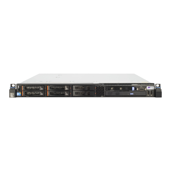
1A: Q NSTALL THE ERVER UICK TART ETUP ROCEDURES Power on the SR Power up a 300 Model A. Make sure the power adapter is plugged into the back of the chassis and connected to the power cord. B. Plug the power cord into a power source with an appropriate rating. WARNING: It is strongly suggested you use an uninterruptible power supply. -
Page 33: Power Up A 505 Model
1A: Q NSTALL THE ERVER UICK TART ETUP ROCEDURES Power up a 505 Model A. Make sure the power cord is plugged into the back of the chassis. B. Plug the power cord into a power source with an appropriate rating. WARNING: It is strongly suggested you use an uninterruptible power supply. -
Page 34: Hyperterminal Setup Procedures
1A: Q NSTALL THE ERVER UICK TART ETUP ROCEDURES HyperTerminal Setup Procedures If using a serial console, follow these procedures on a Windows XP machine to create a HyperTerminal session. NOTE: HyperTerminal is no longer included with Windows as of Microsoft’s Vista system. Please note on Microsoft’s Web page “What happened to HyperTerminal?”... - Page 35 1A: Q NSTALL THE ERVER UICK TART ETUP ROCEDURES C. At the Connect using field, select the COM port assigned to the serial port on the laptop (probably “COM1”), and then click OK to open the Properties dialog box, displaying the Port Settings tab: D.
- Page 36 1A: Q NSTALL THE ERVER UICK TART ETUP ROCEDURES F. In the HyperTerminal session window, go to File > Properties to open the Prop- erties dialog box, displaying the Connect To and Settings tabs: G. Click the Settings tab, and at the Emulation menu select “VT100”. H.
-
Page 37: Login Screen
1A: Q NSTALL THE ERVER UICK TART ETUP ROCEDURES Login screen The login screen displays after powering on the SR unit using a monitor and keyboard, or after creating a HyperTerminal session. NOTES: If using a HyperTerminal session, the login screen will display with black text on a white background. -
Page 38: Quick Start Setup
1A: Q NSTALL THE ERVER UICK TART ETUP ROCEDURES Quick Start setup A. At the Press the number of your selection prompt, press 2 to select the “Quick Start setup” process. The Quick Start setup process takes you to the following configuration screens to make entries: •... -
Page 39: Configure Network Interface Lan1
1A: Q NSTALL THE ERVER UICK TART ETUP ROCEDURES Configure network interface LAN1 A. From the Quick Start menu, press 3 to go to the Configure Network Interface screen for LAN1. B. At the Enter interface LAN1 IP address prompt, type in the LAN1 IP address and press Enter. -
Page 40: Time Zone Regional Setting
1A: Q NSTALL THE ERVER UICK TART ETUP ROCEDURES Time Zone regional setting A. From the Quick Start menu, press 8 to go to the Time Zone regional configura- tion screen. B. Select a region using up-arrow and down-arrow keys. Press Y when you have selected the appropriate region, or press Esc to cancel this change. -
Page 41: Non-Quick Start Procedures Or Settings
1A: Q NSTALL THE ERVER UICK TART ETUP ROCEDURES Non-Quick Start procedures or settings The options described below do not pertain to the quick start setup process. Reboot system A. From the Quick Start menu, press B to go to the Reboot confirmation screen. B. -
Page 42: System Status Screen
1A: Q NSTALL THE ERVER UICK TART ETUP ROCEDURES System Status screen The System Status screen contains the following information: • Serial Number assigned to the chassis • lan1 IP address and netmask specified in screen 3, and current status (“Active” or “Inactive”) •... -
Page 43: Step 1B: Lcd Panel Setup Procedures
1B: LCD P NSTALL THE ERVER ANEL ETUP ROCEDURES Step 1B: LCD Panel Setup Procedures Storage Device Setup (for Attached Storage Units) If you have a NAS (Fibre Channel Connected Storage Device or “SAN”) that will be used with the SR, you will need to connect it to the SR at this point. Refer to Appendix A at the end of this document for instructions on how to connect the Fibre Channel Connected Storage Device. -
Page 44: Lcd Menu
1B: LCD P NSTALL THE ERVER ANEL ETUP ROCEDURES LCD Menu The LCD Menu tree includes the following two main menu selections: • LCD Options - This choice includes options for viewing the LCD display and monitoring the SR once it is configured and running on the network. Information about using LCD Options is included in this document after the M86 menu sub- section. -
Page 45: Ip / Lan1 And 2
1B: LCD P NSTALL THE ERVER ANEL ETUP ROCEDURES IP / LAN1 and 2 When the IP / LAN 1 (2) option is selected, the IP / LAN 1 (2) screen displays with the following menu items: • Configure LAN 1 (2) IP •... -
Page 46: Host Name
1B: LCD P NSTALL THE ERVER ANEL ETUP ROCEDURES Host Name When the Host Name option is selected, the Host Name screen displays with the Configure Host name menu item. A. Choose Configure Hostname and press the checkmark key to go to the Configure Hostname screen. -
Page 47: Non-Quick Start Procedures Or Settings
1B: LCD P NSTALL THE ERVER ANEL ETUP ROCEDURES Non-Quick Start procedures or settings The options described below do not pertain to the quick start setup process. SR Patch Level When the SR Patch Level option is selected, “Security Reporter” and the version number of the currently installed software build displays. -
Page 48: Lcd Options Menu
1B: LCD P NSTALL THE ERVER ANEL ETUP ROCEDURES LCD Options menu When “LCD Options >” is selected, the following menu items display on the screen: Heartbeat, Backlight, LCD Controls >. Make a selection from the menu, and press the checkmark / ENTER key to go to that screen. Heartbeat When the Heartbeat option is selected, the Heartbeat screen displays. -
Page 49: Step 2: Physically Connect The Unit To The Network
2: P NSTALL THE ERVER HYSICALLY ONNECT THE NIT TO THE ETWORK Step 2: Physically Connect the Unit to the Network Now that your SR network parameters are set, you can physically connect the unit to your network. This step requires a standard CAT-5E cable. An additional CAT- 5E cable is required if an Ethernet Tap unit will be installed for bandwidth moni- toring. -
Page 50: Bandwidth Management
2: P NSTALL THE ERVER HYSICALLY ONNECT THE NIT TO THE ETWORK B. Plug the other end of the CAT-5E cable into an open port on the network hub to which the Web-access logging device (Web Filter or SWG) is connected. Bandwidth Management If you choose to install an Ethernet Tap for bandwidth monitoring, you will need to connect it to the SR at this point. -
Page 51: Step 3: Access The Sr And Its Applications Online
3: A NSTALL THE ERVER CCESS THE AND ITS PPLICATIONS NLINE Step 3: Access the SR and its Applications Online Next you will access the SR and its applications online. For this step you will need your network administrator to provide you the following information: •... -
Page 52: Accept The Security Certificate In Firefox
3: A NSTALL THE ERVER CCESS THE AND ITS PPLICATIONS NLINE Accept the Security Certificate in Firefox A. If using a Firefox browser, in the page “This Connection is Untrusted,” click the option I Understand the Risks: B. In the next set of instructions that display, click Add Exception...: Clicking Add Exception opens the Add Security Exception window: M86 S ECURITY... - Page 53 3: A NSTALL THE ERVER CCESS THE AND ITS PPLICATIONS NLINE C. In the Add Security Exception window, click Get Certificate and wait a few seconds until the security certificate is obtained by the server. D. With the checkbox Permanently store this exception selected, click Confirm Security Exception to open the Security Reporter login window: Proceed to Accept the End User License Agreement.
-
Page 54: Temporarily Accept The Security Certificate In Ie
3: A NSTALL THE ERVER CCESS THE AND ITS PPLICATIONS NLINE Temporarily Accept the Security Certificate in IE If using an IE browser, in the page “There is a problem with this website's security certificate.”, click Continue to this website (not recommended): Selecting this option displays the Security Reporter login window with the address field and the Certificate Error button to the right of the field shaded a reddish color: Proceed to Accept the End User License Agreement. -
Page 55: Accept The Security Certificate In Safari
3: A NSTALL THE ERVER CCESS THE AND ITS PPLICATIONS NLINE Accept the Security Certificate in Safari A. If using a Safari browser, the window explaining "Safari can't verify the identity of the website..." opens: Click Show Certificate to open the certificate information box at the bottom of this window: B. -
Page 56: Accept The Security Certificate In Chrome
3: A NSTALL THE ERVER CCESS THE AND ITS PPLICATIONS NLINE Accept the Security Certificate in Chrome A. If using a Chrome browser, in the page “This is probably not the site you are looking for!” click the button Proceed anyway: Clicking this button launches the Security Reporter login window: NOTE: The Security Certificate must be accepted each time a new browser is launched. -
Page 57: Accept The End User License Agreement
3: A NSTALL THE ERVER CCESS THE AND ITS PPLICATIONS NLINE Accept the End User License Agreement A. In the Security Reporter login window, enter your Username and Password, and then click Login to proceed: You may be prompted to accept a security exception for the SR application, after which the EULA Agreement dialog box opens: B. -
Page 58: Log In To The Security Reporter Wizard
3: A NSTALL THE ERVER CCESS THE AND ITS PPLICATIONS NLINE Log in to the Security Reporter Wizard A. In the Username field of the Login window, type in the username specified in the Configure setup wizard user screen of the Quick Start Setup Procedures (Step 1A), or the Configure Setup Wizard User screen in LCD Panel Setup Procedures (Step 1B): B. -
Page 59: Enter Main Administrator Criteria
3: A NSTALL THE ERVER CCESS THE AND ITS PPLICATIONS NLINE • Bandwidth Range and Web Filter Setup sections, if using one or more Web Filters with this SR. • Secure Web Gateway Setup section, if using one or more SWG policy servers with this SR. -
Page 60: For Swgs: Go To Secure Web Gateway Setup
3: A NSTALL THE ERVER CCESS THE AND ITS PPLICATIONS NLINE C. Click the “Set as Source” checkbox if this Web Filter will be designated the primary Web Filter to be associated with the Security Reporter. Otherwise, leave the checkbox blank. D. -
Page 61: Step 4: Generate Ssl Certificate
4: G SSL C NSTALL THE ERVER ENERATE ERTIFICATE Step 4: Generate SSL Certificate Generate a Self-Signed Certficate for the SR This step requires you to generate a self-signed certificate so your browser will recognize the SR as an accepted device. A. - Page 62 4: G SSL C NSTALL THE ERVER ENERATE ERTIFICATE d. Locality (City) - Name of your organization’s city or principality, such as Orange. e. State or Province Name - Full name of your state or province, such as California. f. Country - Two-character code for your country, such as US. g.
-
Page 63: Ie Security Certificate Installation Procedures
4: G SSL C NSTALL THE ERVER ENERATE ERTIFICATE IE Security Certificate Installation Procedures Accept the Security Certificate in IE Go to the appropriate sub-section if using the following Windows operating system and IE browser: • Windows XP or Vista with IE 8 or 9 •... - Page 64 4: G SSL C NSTALL THE ERVER ENERATE ERTIFICATE Figure A2: Windows XP, IE 8 B. Click Certificate Error to open the Certificate Invalid box: Figure B: Windows XP, IE 8 C. Click View certificates to open the Certificate window that includes the host- name you assigned to the SR: M86 S ECURITY...
- Page 65 4: G SSL C NSTALL THE ERVER ENERATE ERTIFICATE Figure C: Windows XP, IE 8 D. Click Install Certificate... to launch the Certificate Import Wizard: Figure D: Windows XP, IE 8 E. Click Next > to display the Certificate Store page: Figure E: Windows XP, IE 8 M86 S ECURITY...
- Page 66 4: G SSL C NSTALL THE ERVER ENERATE ERTIFICATE F. Choose the option “Place all certificates in the following store” and then click Browse... to open the Select Certificate Store box: Figure F: Windows XP, IE 8 G. Choose “Trusted Root Certification Authorities” and then click OK to close the box.
-
Page 67: Windows 7 With Ie 8 Or 9
4: G SSL C NSTALL THE ERVER ENERATE ERTIFICATE Now that the security certificate is installed, you will need to map the SR’s IP address to its hostname. Proceed to Map the SR’s IP Address to the Server’s Hostname. Windows 7 with IE 8 or 9 A. -
Page 68: Map The Sr's Ip Address To The Server's Hostname
4: G SSL C NSTALL THE ERVER ENERATE ERTIFICATE Now that the security certificate is installed, you will need to map the SR’s IP address to its hostname. Proceed to Map the SR’s IP Address to the Server’s Hostname. Map the SR’s IP Address to the Server’s Hostname A. - Page 69 4: G SSL C NSTALL THE ERVER ENERATE ERTIFICATE C. Enter a line in the hosts file with the SR’s IP address and its hostname—the latter entered during the Configure host name screen of the Quick Start Setup Procedures (Step 1A), or the Host Name screen in LCD Panel Setup Proce- dures (Step 1B)—and then save and close the file.
-
Page 70: Step 5: Add Web Filter, Swg To Device Registry
5: A , SWG NSTALL THE ERVER ILTER EVICE EGISTRY Step 5: Add Web Filter, SWG to Device Registry Before you begin configuring the Web Filter and/or SWG to send logs to the SR, you will need to add the Web Filter/SWG in the SR’s Device Registry panel if the device(s) was/were not added during the SR Wizard installation process in Step 3. -
Page 71: Add An Swg Device
5: A , SWG NSTALL THE ERVER ILTER EVICE EGISTRY Add an SWG Device A. At the bottom of the Device Registry panel, click New SWG Policy Server to open the New SWG Policy Server window: The following information displays and cannot be edited: Device Type (SWG), ID, Username. -
Page 72: Step 6: Set Up Web Filter, Swg Log Transfers
6: S , SWG L NSTALL THE ERVER ET UP ILTER RANSFERS Step 6: Set up Web Filter, SWG Log Transfers This step can be performed any time during SR setup, but must be completed in order for the SR to receive logs from the Web Filter and/or SWG. Web Filter Setup Web Filter Configuration A. -
Page 73: Web Filter Log Transfer Verification
6: S , SWG L NSTALL THE ERVER ET UP ILTER RANSFERS Web Filter Log Transfer Verification You can see if log files have transferred by following these steps in the SR: A. Access the System Configuration administrator console. B. Go to the Database pull-down menu and choose Tools to display the Tools screen: C. -
Page 74: Set Self-Monitoring
6: S , SWG L NSTALL THE ERVER ET UP ILTER RANSFERS Set Self-Monitoring A. In the SR Report Manager navigation toolbar, select Administration > System Configuration to display the Server Status panel screen of the System Config- uration administrator console. B. -
Page 75: Use Single Sign-On Access
6: S , SWG L NSTALL THE ERVER ET UP ILTER RANSFERS Use Single Sign-On Access Single Sign-On Access If using a Web Filter, the Single Sign-On (SSO) access feature is available for the global administrator account set up during the wizard hardware installation process. -
Page 76: Swg Setup
6: S , SWG L NSTALL THE ERVER ET UP ILTER RANSFERS SWG Setup Setup instructions differ depending on the SWG software version to be used with the SR (10.0 or 9.2.5). SWG Configuration for Software Version 10.0 Configure SWG to Send Logs to the SR A. -
Page 77: Policy Settings
6: S , SWG L NSTALL THE ERVER ET UP ILTER RANSFERS Policy Settings A. Navigate to Policies > Default Policy Settings and verify if the settings in Enable Emergency Policy and Default Policy Values are the ones you wish to use for sending logs to the SR. -
Page 78: Swg Configuration For Software Version 9.2.5
6: S , SWG L NSTALL THE ERVER ET UP ILTER RANSFERS SWG Configuration for Software Version 9.2.5 Configure SWG to Send Logs to the SR A. Access the SWG user interface. B. Navigate to Administration > System Settings > M86 Devices. C. - Page 79 6: S , SWG L NSTALL THE ERVER ET UP ILTER RANSFERS C. Make your selections from the pull-down menu(s). D. Click Save to save your edit(s). M86 S ECURITY NSTALLATION UIDE...
-
Page 80: Conclusion
6: S , SWG L ONCLUSION ET UP ILTER RANSFERS ONCLUSION Congratulations; you have completed the SR installation procedures. Now that the SR server is set up on your network you will need to be sure the Web-access logging device you are using is sending log files to the SR database. Once the SR database is populated—this generally takes a full day—the Report Manager can be used for generating reports. -
Page 81: Best Reporting Practices
EPORTING RACTICES EPORTING RACTICES This Best Reporting Practices section is provided to help you get started using the Report Manager user interface. The main areas of focus in this section are produc- tivity reporting, security reporting, and real time reporting. In the Productivity Reports Usage Scenarios sub-section you will learn how to: •... -
Page 82: Productivity Reports Usage Scenarios
EPORTING RACTICES RODUCTIVITY EPORTS SAGE CENARIOS Productivity Reports Usage Scenarios This collection of productivity reporting scenarios is designed to help you use the Report Manager to create typical snapshots of end user Internet activity. Each scenario is followed by setup information. Please consult the “How to” section in the index of the Security Reporter User Guide for pages containing detailed, step- by-step instructions on configuring and/or using the tools and features described in that scenario. -
Page 83: Step B: Further Investigate Using A Summary Drill Down Report
EPORTING RACTICES RODUCTIVITY EPORTS SAGE CENARIOS This report shows the top 20 categories that were most frequently visited by users yesterday. Review the list of categories in this canned report. In a later step you will need to select the category to be further investigated. NOTE: Click the left or right arrow in the dashboard to view additional thumbnails. - Page 84 EPORTING RACTICES RODUCTIVITY EPORTS SAGE CENARIOS Note that the drill down report view has been generated for today’s activity by default. To continue this investigation using data from yesterday’s Summary Report, you must create a new report from this current report view by first changing the date scope.
-
Page 85: Step C: Create A New Report Using Yesterday's Date Scope
EPORTING RACTICES RODUCTIVITY EPORTS SAGE CENARIOS Step C: Create a new report using yesterday’s date scope 1. At the bottom of the Summary Drill Down Report view, navigate to Report Settings > Run to open the Run Report window: 2. By default, “Daily” displays in the Date Scope field. Choose “Yesterday” from this menu. -
Page 86: Step E: Create A Detail Drill Down Report To Obtain A List Of Urls
EPORTING RACTICES RODUCTIVITY EPORTS SAGE CENARIOS After executing the last command, note that user IP addresses now display in the first column of the report view instead of categories. In the Security Reporter User Guide index, see: • How to: use count columns and links For the last step of this exercise, you will select a user from the current Summary Drill Down Report view and then drill down further to see which URLs that user visited, thereby creating a Detail Drill Down Report view. - Page 87 EPORTING RACTICES RODUCTIVITY EPORTS SAGE CENARIOS Note that the Detail Drill Down Report view contains columns of information pertaining to the user’s machine and setup on the network, sites visited, cate- gorized URLs, and clickable links to access pages the user viewed. 2.
-
Page 88: Ii. 'Group By' Report And Export Report Exercise
EPORTING RACTICES RODUCTIVITY EPORTS SAGE CENARIOS II. ‘Group By’ Report and Export Report exercise In this exercise you will learn how to display only the top 10 records of a summary drill down ‘group by’ report view, export that report view in the PDF output format, and then view the results of the generated PDF file. -
Page 89: Step B: Modify The Report View To Only Display Top 10 Site Records
EPORTING RACTICES RODUCTIVITY EPORTS SAGE CENARIOS Note that URLs/IP addresses of sites users visited in the category now display in the first column of the modified report view, instead of category names. In the Security Reporter User Guide index, see: •... -
Page 90: Step C: Export The Report View In The Pdf Output Format
EPORTING RACTICES RODUCTIVITY EPORTS SAGE CENARIOS Step C: Export the report view in the PDF output format 1. To export the current report view in the PDF format, at the bottom of the report view click Export All to open the Export window: By default, “PDF”... -
Page 91: Iii. Save And Schedule A Report Exercise
EPORTING RACTICES RODUCTIVITY EPORTS SAGE CENARIOS 3. Print or save the PDF file using available tools or icons in the PDF file window, or close the PDF file. In the Security Reporter User Guide index, see: • How to: export a summary Drill Down Report •... -
Page 92: Step B. Schedule A Recurring Time For The Report To Run
EPORTING RACTICES RODUCTIVITY EPORTS SAGE CENARIOS 3. Choose the Save and Schedule option from the “save” options at the bottom of the window. The three “save” options are as follows: • Save and Schedule - this option lets you save criteria from the current report view and then set up a schedule to run the report using that criteria. -
Page 93: Iv. Create A Custom Category Group And Generate Reports
EPORTING RACTICES RODUCTIVITY EPORTS SAGE CENARIOS In the Security Reporter User Guide index, see: • How to: schedule a Drill Down report to run You have now learned how to save a report and schedule the report to run at a designated time. -
Page 94: Step B: Run A Report For A Specified Custom Category Group
EPORTING RACTICES RODUCTIVITY EPORTS SAGE CENARIOS In the Security Reporter User Guide index, see: • How to: add a Custom Category Group Step B: Run a report for a specified Custom Category Group 1. To create a report for a Custom Category Group, choose Reports > Drill Down Reports >... - Page 95 EPORTING RACTICES RODUCTIVITY EPORTS SAGE CENARIOS 2. Choose an existing user group from the User Groups list and then click New to display the New User Groups panel: 3. Type in the Group Name and check the box(es) corresponding to “Patterns”, “IP Ranges”, and/or “Single Users/Exclude”...
-
Page 96: Step B: Generate A Report For A Custom User Group
EPORTING RACTICES RODUCTIVITY EPORTS SAGE CENARIOS Step B: Generate a report for a custom User Group Once the custom User Group is recognized by the SR (on the following day), reports can be generated. There are two ways to generate a summary or detail report for a custom User Group. -
Page 97: Security Reports Usage Scenarios
EPORTING RACTICES ECURITY EPORTS SAGE CENARIOS Security Reports Usage Scenarios This collection of reporting scenarios is tailored towards familiarizing you with tools for generating, exporting, saving, and scheduling basic security reports. Each scenario is followed by user interface access information. Please consult the “How to”... -
Page 98: Step B: Navigate To The Security Policy Violations Report
EPORTING RACTICES ECURITY EPORTS SAGE CENARIOS Step B: Navigate to the Security Policy Violations report Click the Security Policy Violations tab to display the the Security Policy Viola- tions report view: This report provides information on each instance in which an end user breached a security policy. -
Page 99: Step D: Navigate To The Rule Transactions Report
EPORTING RACTICES ECURITY EPORTS SAGE CENARIOS Step D: Navigate to the Rule Transactions report Click the Rule Transactions tab to display the Rule Transactions report view: This report includes each instance in which an end user triggered a threshold in an SWG Security Policy. -
Page 100: Ii. Create A Drill Down Security Report View
EPORTING RACTICES ECURITY EPORTS SAGE CENARIOS • Click this icon to re-display the top six graphs and table of records (the default view) • Click this icon to display the table of records only: In the Security Reporter User Guide index, see: •... -
Page 101: Exercise B: Create A Detail Report View
EPORTING RACTICES ECURITY EPORTS SAGE CENARIOS Note that this report view looks similar to a basic security report view, with the following exceptions: • breadcrumb trail beneath the navigation toolbar shows the path of the current report view • first column of report view corresponds to the column selection you made to create this report view •... - Page 102 EPORTING RACTICES ECURITY EPORTS SAGE CENARIOS The detail report view shows a table of records with columns for Date, User IP, User name path, Site name, Bandwidth (if clicking a Bandwidth link), and URL. Note the following buttons are available at the bottom right of the panel: •...
-
Page 103: Iii. Create A Customized Security Report
EPORTING RACTICES ECURITY EPORTS SAGE CENARIOS III. Create a customized Security Report Once you become familiar with the basic four security reports and their reporting tools, you may want to create your own customized reports. This exercise will show you two different methods for running security reports. One method is by using the Report Wizard >... - Page 104 EPORTING RACTICES ECURITY EPORTS SAGE CENARIOS • By Specific User - If selecting this option, enter the end user name—using the ‘%’ wildcard to return multiple usernames—and then click Preview Users to display query results in the list box below. •...
-
Page 105: Exercise B: Use The Report Wizard To Run A Custom Report
EPORTING RACTICES ECURITY EPORTS SAGE CENARIOS Exercise B: Use the Report Wizard to run a custom report 1. Navigate to Reports > Security Reports > Report Wizard to display the Secu- rity Report Wizard panel where you specify criteria to include in the report you wish to generate: 2. - Page 106 EPORTING RACTICES ECURITY EPORTS SAGE CENARIOS • Predefined Ranges - If choosing this default option, make a selection from the pull-down menu: “Today” (default), “Month to Date”, “Year to Date”, “Yesterday”, “Month to Yesterday”, “Year to Yesterday”, “Last Week”, “Last Weekend”, “Current Week”, “Last Month”.
-
Page 107: Iv. Export A Security Report
EPORTING RACTICES ECURITY EPORTS SAGE CENARIOS IV. Export a Security Report In this exercise you will learn how to export the current basic security report view in the PDF format. Step A: Specify records to include in the report With a basic security report generated, go to the bottom right of the panel and either click Export All Records, or choose specific records from the table and then click Export Selected. -
Page 108: Step D: View The Exported Security Report
EPORTING RACTICES ECURITY EPORTS SAGE CENARIOS Step D: View the exported Security Report The generated basic Security Report PDF file includes the following information: The header of the generated report includes the date range, report type, and report criteria, and report description. The footer of the report includes the date and time the report was generated (M/D/ YY, HH:MM:SS AM/PM), administrator login ID (Generated By), and Page number and page range. -
Page 109: Save A Security Report
EPORTING RACTICES ECURITY EPORTS SAGE CENARIOS At the end of the report, the Total Items display for all records. In the Security Reporter User Guide index, see: • How to: export a Security Report V. Save a Security Report A basic security report is saved by using the Security Report Wizard. The Wizard is accessible by either creating a report view and then selecting Report Wizard >... -
Page 110: Step B: Specify Criteria In Report Details
EPORTING RACTICES ECURITY EPORTS SAGE CENARIOS Step B: Specify criteria in Report Details 1. In Report Details, type in the Report Name. 2. Specify the Report Time Span by choosing one of two options: • Predefined Ranges - If choosing this option, make a selection from the pull- down menu: “Today”... -
Page 111: Step C: Select The Users Or Group In Users
EPORTING RACTICES ECURITY EPORTS SAGE CENARIOS Step C: Select the users or group in Users In Users, select one of the accordions and indicate criteria to include in the report to be generated: • By User Group - If selecting this option, choose the User Group for your report query results. -
Page 112: Access The Saved Reports Panel
EPORTING RACTICES ECURITY EPORTS SAGE CENARIOS Access the Saved Reports panel A saved security report can be edited any time as follows: 1. Navigate to Reports > Saved Reports. 2. Select the report name from the list: 3. Click Edit to go to the Security Report Wizard panel where the report can be updated and saved. -
Page 113: Vi. Schedule A Security Report To Run
EPORTING RACTICES ECURITY EPORTS SAGE CENARIOS VI. Schedule a Security Report to run A basic security report is scheduled to run by using either the Schedule Settings window in the Security Report Wizard, or the Report Schedule panel. The Schedule Settings window is accessible via Report Wizard > Schedule or Security Reports >... - Page 114 EPORTING RACTICES ECURITY EPORTS SAGE CENARIOS 5. Specify the Group By selection from available choices in the pull-down menu. 6. By default, Save report with URLs is de-selected. Click this checkbox to select this option, and then specify the number of URLs to save: •...
-
Page 115: Exercise B: Use The Wizard To Create And Schedule Reports
EPORTING RACTICES ECURITY EPORTS SAGE CENARIOS a. Enter a Schedule Name. b. Select the Frequency to run the report from the pull-down menu (Daily, Weekly, or Monthly). If Weekly, specify the Day of the Week from the pull-down menu (Sunday - Saturday). -
Page 116: Access The Report Schedule Panel
EPORTING RACTICES ECURITY EPORTS SAGE CENARIOS 3. Choose the Report Type from the pull-down menu (“Blocked Viruses”, “Secu- rity Policy Violations”, “Traffic Analysis”, “Rule Transactions”); by default “Blocked Viruses” displays. 4. Specify the Report Time Span by choosing one of two options: •... -
Page 117: Real Time Reports Usage Scenarios
EPORTING RACTICES EPORTS SAGE CENARIOS Real Time Reports Usage Scenarios This collection of setup and usage scenarios is designed to help you understand and use basic tools in the console for enforcing your Internet usage policy. Each scenario is followed by console setup information. Please consult the “How to” section in the index of the Security Reporter User Guide for pages containing detailed, step-by-step instructions on configuring and/or using the tools and features described in that scenario. -
Page 118: Step B: Navigate Panels In The Policy Section
EPORTING RACTICES EPORTS SAGE CENARIOS • Overall Ranking - view details about current gauge activity for all end users affecting gauges • Lockouts - prevent the end user from accessing specified URLs, the Internet, or the entire network • Add/Edit Gauges - create and maintain gauges used for monitoring end users’ Internet activity •... - Page 119 EPORTING RACTICES EPORTS SAGE CENARIOS NOTE: The Gauge Ranking panel is also accessible by right-clicking a dashboard gauge and then selecting View Gauge Ranking from the menu. 2. Find the library category with the highest score, and click that score to open the Category View User panel: Note the left side of this panel is populated with rows of records for Categories affected by the selected end user.
-
Page 120: Step B: Investigate A User's Activity In A Specified Gauge
EPORTING RACTICES EPORTS SAGE CENARIOS Step B: Investigate a user’s activity in a specified gauge 1. To find out which URLs the top end user visited in the high-scoring library cate- gory, select the category with the highest score and then click it to display a list of URLs the user visited in the right side of this panel: 2. -
Page 121: Step C: Investigate The User's Internet Activity In Other Gauges
EPORTING RACTICES EPORTS SAGE CENARIOS Step C: Investigate the user’s Internet activity in other gauges 1. To find out which other gauges the same user is currently affecting, return to the Gauge Ranking table by going to the lower left corner of the Category View User panel and clicking the Back button. -
Page 122: Iii. Create A Gauge Exercise
EPORTING RACTICES EPORTS SAGE CENARIOS 4. To find out which URLs the user is viewing in a particular library category, choose the category from the list, and then click the URL in the URLs list. In the Security Reporter User Guide index, see: •... -
Page 123: Step B: Add A Url Gauge
EPORTING RACTICES EPORTS SAGE CENARIOS In the Security Reporter User Guide index, see: • How to: access the Add/Edit Gauges panel Step B: Add a URL Gauge 1. Click New Gauge at the bottom left of the panel to open the URL Gauge panel: 2. - Page 124 EPORTING RACTICES EPORTS SAGE CENARIOS 5. From the Available User Groups list, select the user group to highlight it. 6. Click Add to move the user group to the Assigned User Groups list box. 7. After adding user groups, click Save at the bottom right of the panel to return to the Add/Edit Gauges panel that now includes the name of the gauge you just added: In the Security Reporter User Guide index, see:...
-
Page 125: Iv. Create An Email Alert Exercise
EPORTING RACTICES EPORTS SAGE CENARIOS Now that you know the basics of creating a gauge, you will soon be able to create and use gauges to monitor various groups of users who frequent URLs in library categories you wish to restrict, and deal in real time with Internet usage issues that endanger your network and/or consume an excessive amount of bandwidth resources. - Page 126 EPORTING RACTICES EPORTS SAGE CENARIOS 4. Type in the Alert Name to be used for the alert that will be delivered to the group administrator. 5. Specify the User Threshold ceiling of gauge activity that will trigger the alert. The default and recommended value is 200 for a URL gauge. 6.
-
Page 127: Step B: Select Email Alert Action
EPORTING RACTICES EPORTS SAGE CENARIOS Step B: Select Email Alert Action 1. In the Alert Action section, choose the “Email” alert notification option. Note that this action opens and activates the Email Addresses accordion at the right side of the panel. 2. -
Page 128: Step C: Receiving An Email Alert
EPORTING RACTICES EPORTS SAGE CENARIOS Step C: Receiving an email alert When an end user’s activity in a gauge reaches the threshold limit established for an alert, it triggers an alert notification. If the email alert option was selected, an email is sent to the email address that was specified. -
Page 129: Important Information About Using The Sr In The Evaluation Mode
MPORTANT NFORMATION ABOUT USING THE IN THE VALUATION EPORT ANAGER MPORTANT NFORMATION ABOUT USING THE VALUATION Evaluation mode pertains to the state of an SR in which a maxmum of three weeks of data is stored on the server. When evaluating the SR in evaluation mode, the Report Manager user interface and Expiration screen from the System Configuration administrator console display differently than they do in registered (standard) mode. -
Page 130: System Configuration
MPORTANT NFORMATION ABOUT USING THE IN THE VALUATION YSTEM ONFIGURATION System Configuration NOTE: See Appendix C: Evaluation Mode in the Security Reporter User Guide for infor- mation about changing the SR’s mode from evaluation to registered. Evaluation Mode Pop-Up In evaluation mode, the SR Status pop-up box opens when accessing the System Configuration administrator console: Until the SR is in registered mode, this pop-up box will continue to open whenever accessing the System Status screen of the System Configuration administrator... -
Page 131: Led Indicators And Buttons
LED I 500, 700 730 M NDICATORS AND UTTONS RONT ONTROL ANELS ON ODELS LED I NDICATORS AND UTTONS Front Control Panels on 500, 700 and 730 Models Control panel buttons, icons, and LED indicators display on the right side of a 500, 700 and 730 model’s front panel. -
Page 132: Rear Panel On The 700 And 730 Model
LED I 730 M NDICATORS AND UTTONS ANEL ON THE ODEL Rear Panel on the 700 and 730 Model Power Supplies (LED indicators) – The power supplies are located at the right on the rear of the chassis. An LED indicator is located above each of the power plugs. UID (LED indicator) –... -
Page 133: Chassis Panel On A 505 Model
LED I 505 M NDICATORS AND UTTONS HASSIS ANEL ON A ODEL Chassis Panel on a 505 Model For diagrams and descriptions of the 505 model’s front and rear panel components and their usage, please see “Server controls, LEDs, and power” in the IBM System x3250 M3 Types 4251, 4252, and 4261 Installation and User's Guide. -
Page 134: Chassis Panels On 705 And 735 Models
LED I 735 M NDICATORS AND UTTONS HASSIS ANELS ON ODELS Chassis Panels on 705 and 735 Models For diagrams and descriptions of the 705 and 735 model’s front and rear panel components and their usage, please see “Server controls, LEDs, and power” in the IBM System x3620 M3 Type 7376 Installation and User's Guide. -
Page 135: Regulatory Specifications And Disclaimers
EGULATORY PECIFICATIONS AND ISCLAIMERS ECLARATION OF THE ANUFACTURER OR MPORTER EGULATORY PECIFICATIONS AND ISCLAIMERS The information in this section pertains to SR models 300, 500, 700, and 730. Declaration of the Manufacturer or Importer Safety Compliance USA: UL 60950-1 1st ed. 2007 Europe: Low Voltage Directive (LVD) 2006/95/EC to CB Scheme IEC 60950-1: 2001 Canada... -
Page 136: Ec Declaration Of Conformity
EGULATORY PECIFICATIONS AND ISCLAIMERS ECLARATION OF THE ANUFACTURER OR MPORTER EC Declaration of Conformity European Community Directives Requirement (CE) Declaration of Conformity Manufacturer’s Name: M86 Security 828 W. Taft Avenue Manufacturer’s Address: Orange, CA 92865 Application of Council Directive(s): Low Voltage •... -
Page 137: Ppendix A: Fibre Hannel Onnected Torage Evice
A: F PPENDIX IBRE HANNEL ONNECTED TORAGE EVICE RELIMINARY ETUP ROCEDURES A: F PPENDIX IBRE HANNEL ONNECTED TORAGE EVICE This appendix pertains to the installation of the optional NAS (Fibre Channel Connected Storage Device or “SAN”) unit. Preliminary Setup Procedures Unpack the Unit from the Carton Inspect the packaging container for evidence of mishandling during transit. -
Page 138: Rack Mount The Server
A: F PPENDIX IBRE HANNEL ONNECTED TORAGE EVICE RELIMINARY ETUP ROCEDURES Rack Mount the Server Rack Mount Components The following items are needed to install rails for rack mounting: • 1 slide kit and mounting hardware • 1 pair Accuride slide rails Rack Setup Precautions WARNING: Before rack mounting the unit, the physical environment should be set up to safely... -
Page 139: Step 1
A: F PPENDIX IBRE HANNEL ONNECTED TORAGE EVICE RELIMINARY ETUP ROCEDURES Step 1 Remove inner slide rail as shown. Press down on latch to release. Step 2 Attach inner slide rail to chassis using 3 screws as shown. NOTE: When attaching the extended brackets, attach them loosely at first. Adjust the length to fit the cabinet, and then tighten. -
Page 140: Step 4
A: F PPENDIX IBRE HANNEL ONNECTED TORAGE EVICE RELIMINARY ETUP ROCEDURES Step 4 Attach left and right front (short) extended brackets to the outer rail using 2 screws, 2 washers, and 2 nuts for each bracket. NOTE: Make sure the flange is on the bottom edge. Step 5 Attach outer rail to chassis using 4 screws and cage nuts per rail, 2 at each end. -
Page 141: Install The Unit
A: F PPENDIX IBRE HANNEL ONNECTED TORAGE EVICE NSTALL THE Install the Unit Link the SR Unit with the Fibre Channel Connected Device This step is a continuation from the Storage Device Setup (for Attached Storage Units) portion of Step 1A or 1B in the SR section. The procedures outlined in this step require the use of a CAT-5E crossover cable and the fibre channel cable. -
Page 142: Step 2: Connect The Storage Device
A: F PPENDIX IBRE HANNEL ONNECTED TORAGE EVICE NSTALL THE Step 2: Connect the Storage Device A. Plug the other end of the fibre channel cable into the storage device’s HOST “1” channel (see Figure 3, Item A). Figure 3: Back of the Nexsan SATABoy B. -
Page 143: Shut Down, Restart Procedures
A: F PPENDIX IBRE HANNEL ONNECTED TORAGE EVICE NSTALL THE Shut Down, Restart Procedures Follow the procedures in this section if you need to shut down or restart the storage device. Shut Down the Storage Device Unit If you need to shut down the storage device, always follow these steps: A. -
Page 144: Physical Components
A: F PPENDIX IBRE HANNEL ONNECTED TORAGE EVICE HYSICAL OMPONENTS Physical Components M86 S ECURITY NSTALLATION UIDE... -
Page 145: Led Display
A: F PPENDIX IBRE HANNEL ONNECTED TORAGE EVICE HYSICAL OMPONENTS LED Display Temperature and Ventilation Status When the LED is green, the blowers are operating at an acceptable RPM, and the internal temperature sensors are within acceptable limits. The LED alternates green and red to indicate a predicted failure of one blower or an alarmingly rapid increase in temperature. -
Page 146: Disc Drive Alarm
A: F PPENDIX IBRE HANNEL ONNECTED TORAGE EVICE HYSICAL OMPONENTS Disc Drive Alarm The LED is illuminated yellow if a drive is suspected to be bad. Disk Drive Activity The LED is illuminated green when an installed drive is in a “ready” state. During activity, the LED will flicker. -
Page 147: Appendix B: Optional Ethernet Tap Installation
B: O PPENDIX PTIONAL THERNET NSTALLATION RELIMINARY ETUP ROCEDURES B: O PPENDIX PTIONAL THERNET NSTALLATION This appendix pertains to the optional installation of the Ethernet Tap unit for band- width monitoring. NOTE: In order to monitor bandwidth on the SR, both inbound and outbound traffic must be sent to the SR through use of a port span, tap, or other similar device. - Page 148 B: O PPENDIX PTIONAL THERNET NSTALLATION NSTALL THE THERNET Diagram showing Ethernet Tap installation on the network If the designated Web Filter has not yet been installed, disregard this sub-step and proceed to sub-step C. C. Using a crossover cable, connect one end to the Switch’s port configured to be the destination port of the Port Mirror.
-
Page 149: Index
NDEX Access the Report Schedule panel 108 Access the Saved Reports panel 104 Add to Report Schedule 84 boot up 300 series server 124 500, 700 series server 123 Change Quick Start password 33 Configure Setup Wizard User 38 Create a customized Security Report 95 Create a gauge 114 Create an email alert 117 crossover cable 6... - Page 150 NDEX IEC 127 Install Tap 139 LCD Panel 21 Login screen 29 LVD 127 Modify report 81 NAS 22 ping the SR 43 Power Supply Precautions 18 Quick Start menu 29 Rack Setup Precautions 8 RAID 137 reboot 33 300 series server 124 500, 700 series server 123 report for a custom user group 88 Reset Admin Account 39...
- Page 151 NDEX UID 123 UL 127 usernames and passwords 67 Web Filter 42 wizard installation procedures 67 M86 S ECURITY NSTALLATION UIDE...
- Page 152 NDEX M86 S ECURITY NSTALLATION UIDE...
- Page 154 ® About Trustwave Trustwave is a leading provider of information security and compliance management solutions to large and small businesses throughout the world. Trustwave analyzes, protects and validates an organization's data management infrastructure from the network to the application layer—to ensure the protection of informa- tion and compliance with industry standards and regulations such as the PCI DSS and ISO 27002, among others.
Need help?
Do you have a question about the M86 Security 300 and is the answer not in the manual?
Questions and answers