Advertisement
D
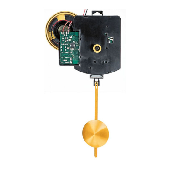
SELVA Funkpendelwerk »FW«
mit Schlag
Das Uhrwerk einbauen
1 – Das Uhrwerk (1) – Zeigerwerk nach oben – flach auf den Werk -
tisch legen. Den Sicherungsstift in der Uhrwerkrückseite noch
nicht entfernen!
2 – Die Zentralschraube (4) von vorne durch das vorgesehene
Zifferblatt/Uhrgehäuse (3) stecken. Die Einschraubtiefe der Zentral -
schraube (4) sollte ca. 2–3 mm betragen. Eine oder evtl. mehrere
Gummi-Unterlegscheiben (2) beilegen.
3 – Das Zifferblatt/Uhrgehäuse (3) mit Zentralschraube (4) auf das
Uhrwerk (1) setzen. Die Zentralschraube (4) in die Gewindebohrung
des Uhrwerks (1) drehen.
4 – Das Zifferblatt/Uhrgehäuse (3) so ausrichten, dass die »12«-Posi-
tion mit den Kanten des Uhrwerks (1) fluchtet. Die Zentral schraube (4)
endgültig festziehen.
5 – Den Lautsprecher entweder in seiner Halterung am Uhrwerk
belassen oder aber im/am Uhrgehäuse befestigen. Bei Befestigung
im/am Uhrgehäuse, für optimalen Klang ein Schall-Loch mit einem
Durchmesser von ca. 55 mm vorsehen. Die Lage des Schall-Lochs
so wählen, dass sich Uhrwerk und Lautsprecher im montierten
Zustand nicht berühren.
6 – Das Schall-Loch von innen mit dünnem Stoff abdecken.
7 – Den Lautsprecher mit kleinen Schräubchen entlang seines äußeren
Durchmessers befestigen.
8 – Den lose verdrahteten Batteriehalter so im/am Uhrgehäuse
montieren, dass er nicht mit dem Pendel in Konflikt geraten kann.
Die Zeiger aufsetzen
1 – Die drei Zeiger (5/6/7) nun jeweils so auf ihre Wellen stecken,
dass sie genau auf die »12« zeigen.
2 – Sicherstellen, dass die Zeiger weder auf dem Zifferblatt streifen
noch sich gegenseitig berühren können.
3 – Den Sicherungsstift (s. Skizze) entfernen.
4 – Zwei 1,5-V-Alkali-Manganzellen (LR 6) seitenrichtig in die Batte -
riehalter am Uhrwerk einlegen, um die Uhr zu starten (Uhrwerk rechts,
Pendelwerk links). Die Zeiger be wegen sich vollautomatisch erst auf
die 4-Uhr-Position (Stillstand 2 min) und dann – nach Emp fang
eines »Zeittelegramms« und dessen interner Verarbeitung innerhalb
von 2 bis max. 10 Minuten – auf die aktuelle Tages zeit. Sollte die
Uhr keinen erf olg reichen Empfang haben, bitte nach ca. 2 Stunden
einen erneuten Ver such starten. Dazu die rechte Batterie (von hinten
gesehen) für ca. 1 min entfernen und anschließend wieder einlegen.
5 – Das Uhrwerk unternimmt jede volle Stunde einen Empfangs-
versuch bzw. Zeitvergleich mit dem Sender.
Das Schlagwerk
1 – Eine 1,5-V-Alkali-Mangan-Babyzelle LR 14 seitenrichtig in den
lose verdrahteten Batteriehalter einlegen.
2 – Die Schalter für die verschiedenen Schlagwerkfunktionen befinden
sich rechts (von hinten gesehen) neben dem Uhrwerk unterhalb der
Lautsprecherhalterung.
0916 466-544-6 DEF
GB
SELVA Radio-Controlled
Pendulum Movement »FW« with Chimes
Installing the Movement
1 – Place the movement (1) – handshafts up – flat on the workbench.
Do not yet remove the safety pin!
2 – Guide the center screw (4) through the center hole of the
dial/clock case (3). Approx. 2–3 mm of thread should project.
If necessary, add one or more rubber washers (2).
3 – Set the dial/clock case (3) with center screw (4) onto the clock
movement (1). Screw the center screw (4) into the threaded center
hole of the movement (1).
4 – Adjust the dial/clock case (3) so that the dial's hour markers
are in line with the edges of the movement (1). Tighten the center
screw (4).
5 – Either leave the loudspeaker in its mount on the movement
or attach it to the clock case. If the latter method is chosen, cut
a hole with a diameter of approx. 55 mm into the case to achieve
the best possible sound. Place the hole so that movement and
loudspeaker do not interfere with one another.
6 – Cover the hole from the inside with a strip of thin fabric.
7 – Mount the loudspeaker with small screws placed along its
outer edge.
8 – Mount the separate battery box in the clock case making sure
that it will not interfere with the movement of the pendulum.
Fitting the Clock Hands
1 – Fit the three clock hands (5/6/7) onto their respective shafts so
that they all point exactly to the »12« on the dial.
2 – Ensure that the hands neither touch the dial nor interfere with
one another.
3 – Remove the safety pin (see sketch).
4 – To start the clock movement, insert two 1.5V alkaline AA cells
into the battery boxes on either side of the movement (time right,
pendulum left side). The hands will now automatically move to the
4 o'clock position, pause for 2 min and then – after receiving a »time
telegram« and identifying the signal, move to the actual time of day
within approx. 2 to 10 min. If the clock movement does not have
proper signal reception, please try again after approx. 2 hrs. by
remov ing the right-hand battery (viewed from the rear) and re-
inserting it after a waiting period of approx. 1 min.
5 – The movement automatically receives time signals at every full
hour.
The Chimes
1 – Insert a 1.5V alkaline C cell into the separate battery box
(watch polarity).
2 – The switches for the various chime selections are located in the
rear of the movement underneath the loudspeaker mount.
3 – Set the second switch from the bottom to the desired chime
melody:
0 = Chimes switched off.
B = Bim-bam chimes.
W = 4/4 Westminster chimes.
4 – The third switch from the bottom controls the automatic chime
silencing: »SUN« symbol: Full chimes without silencing.
F
Mouvement de balancier radio-piloté
« FW » avec sonnerie SELVA
Insérer le mouvement
1 – Poser le mouvement (1) à plat – minuterie vers le haut – sur la
surface de travail. Ne pas encore enlever la goupille de maintien !
2 – Insérer la vis centrale (4) depuis le devant dans le cadran/boîtier (3)
prévu. Le filetage de la vis centrale (4) devrait être d'env. 2–3 mm.
Mettre une ou plusieurs rondelle(s) en caoutchouc (2).
3 – Poser le cadran/boîtier (3) avec la vis centrale (4) sur le
mouvement (1). Visser la vis centrale dans le trou fileté du
mouvement (1).
4 – Centrer le cadran/boîtier (3) de sorte que la position « 12 »
s'aligne avec le bord du mouvement (1). Serrer définitivement la
vis centrale (4).
5 – Laisser le haut-parleur soit dans le support du mouvement soit
le fixer au/dans le boîtier. Dans le deuxième cas, afin de garantir
une sonorité optimale, prévoir un trou de résonance d'un diamètre
de 5,5 mm. Choisir la position du trou de résonance de sorte que le
mouvement et le haut-parleur ne se touchent pas une fois assemblés.
6 – Revêtir le trou de résonance à l'intérieur avec un tissu fin.
7 – Fixer le haut-parleur avec des petites vis à l'extrémité extérieure
du diamètre.
8 – Insérer le support de pile dans le boîtier en veillant qu'il
n'empêche pas l'oscillation du balancier.
Positionner les aiguilles
1 – Mettre les aiguilles (5/6/7) sur leur arbre de sorte qu'elles indiquent
exactement sur le « 12 ».
2 – Vérifier que les aiguilles ne butent pas contre un obstacle ou
ne se touchent pas entre elles.
3 – Enlever la goupille de maintien.
4 – Insérer deux piles alcali-manganèse 1,5 volts (LR 6) correcte-
ment dans le compartiment à piles pour mettre le mouvement en
marche. Ainsi, les aiguilles se positionnent automatiquement sur
04 h 00 (arrêt 2 minutes), puis, après la réception du télégramme
horaire et de son traitement interne (dans les 2 à 10 minutes
suivantes), sur l'heure exacte. Si la pendule n'a pas reçu la
réception, réessayer après 2 heures. Pour ce faire, enlever la pile
de droite (vue dederrière) pendant environ 1 minute, puis insérer à
nouveau la pile.
5 – Le mouvement effectue toutes les heures pleines un essai de
réception ou compare l'heure avec celle de l'émetteur.
Le mouvement de sonnerie
1 – Insérer correctement une pile alcali-manganèse 1,5 volts
(LR 14) dans le compartiment à pile.
2 – Les leviers pour les différentes fonctions du mouvement de
sonnerie sont à côté du mouvement, à droite (vue de derrière)
au-dessous du support du haut-parleur.
3 – Mettre le deuxième levier sur la sonnerie désirée :
0 = sonnerie arrêtée
B = sonnerie bim-bam
W = sonnerie Westminster 4/4
4 – Le troisième levier depuis le bas permet de régler automatique-
ment l'arrêt de sonnerie.
Advertisement
Table of Contents

Subscribe to Our Youtube Channel
Related Manuals for Selva FW

Summary of Contents for Selva FW
- Page 1 SELVA Radio-Controlled Mouvement de balancier radio-piloté mit Schlag Pendulum Movement »FW« with Chimes « FW » avec sonnerie SELVA Das Uhrwerk einbauen Installing the Movement Insérer le mouvement 1 – Poser le mouvement (1) à plat – minuterie vers le haut – sur la 1 –...
- Page 2 3 – Den 2. Schalter von unten auf die gewünschte Schlagart stellen: »MOON« symbol: Starting with the next full hour and for the next Position « soleil » : sonnerie pleine sans arrêt de sonnerie. 8 hrs., the volume of the chimes is reduced to half. If the switch is 0 = Schlag abgeschaltet.
- Page 3 1 – Batteriespannung, -kontakt und -polung überprüfen. 3 – Insert the safety pin. Défaut : La position des aiguilles ne correspond pas à l’heure exacte. 2 – Die Uhr in eine andere Lage bringen, z. B. um 45 oder 90° 1 –...
Need help?
Do you have a question about the FW and is the answer not in the manual?
Questions and answers