Table of Contents
Advertisement
Quick Links
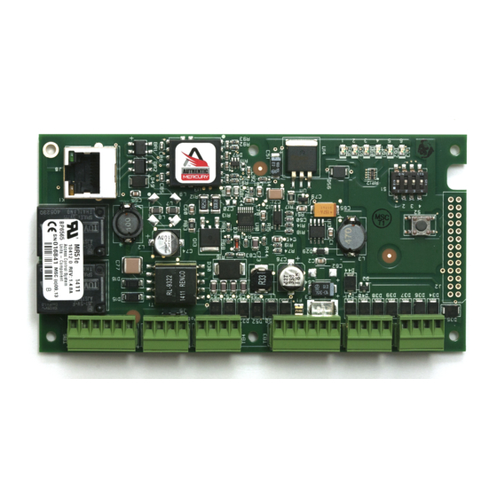
MR51e Reader Interface
Installation and Specifications
1. General:
The MR51e reader interface provides a network connected interface to one physical barrier using single
or paired reader. PoE based solution to the OEM integrator for interfacing TTL (D1/D0, Clock/Data),
F/2F or RS-485 readers to door hardware. The on-board twisted pair Ethernet jack with PoE support
enables easy installation.
control for one physical barrier.
Note: For UL, the Power Sourcing Equipment (PSE) such as a PoE enabled network switch and/or PoE
power injectors must be UL Listed under UL294B.
Reader port 1 can accommodate a reader that utilizes TTL (D1/D0, Clock/Data), F/2F, or RS-485 device
signaling and also provides tri-stated LED control, and buzzer control (one wire LED mode only).
Reader port 2 can accommodate a reader that TTL (D1/D0, Clock/Data), or F/2F signaling, and also
provides tri-stated LED control, and buzzer control (one wire LED mode only). Two Form-C relay
outputs may be used for door strike control or alarm signaling. The relay contacts are rated at 5 A @ 30
Vac/dc, dry contact configuration. Four inputs are provided that may be used for monitoring the door
contacts, exit push buttons, and alarm contacts. Input circuits can be configured as unsupervised or
supervised. The MR51e requires PoE or local 12 Vdc for power. The MR51e may be mounted in a 3-
gang switch box; a mounting plate is supplied with the unit. The MR51e may be mounted in an
enclosure; the supplied mounting plate has mounting holes that match the MR50 mounting footprint.
2. MR51e Hardware:
RESET SWITCH
STATUS LEDs
Mercury Security © 2015
2355 MIRA MAR AVE. LONG BEACH, CA 90815-1755, (562)986-9105 FAX (562) 986-9205
Two reader interfaces configured as paired or alternate readers provide
IN1
IN2
IN3
1
1
TB1
TB2
J2
4
3
2
1
S1
ON
S2
6
5
4
3
0.15 [3.81]
2.55 [64.77]
DIP SWITCH
RLY 2
RLY 1
NC C
NO
NC
C
NO
RELAY K2
LED
(K2)
D24
RELAY K1
LED
(K1)
D19
ETHERNET
STATUS
LEDs
ACT
LNK
MR51e
This device complies with part 15 of the FCC Rules.
Operation is subject to the following two conditions: (1) This
device may not cause harmful interference, and (2) this
device must accept any interference received, including
interference that may cause undesired operation.
IN4
VO LED BZR CLK DAT GND
LED
BZR
CLK
DAT
VO GND
1
1
1
TB3
TB4
PoE
2
1
5.4 [137.16]
STATUS LEDs
DAT
BZR
DAT
BZR
GND
GND
CLK
LED
GND
CLK
LED
5V
1 2 3 4 5 6
3.3V
SOLDER SIDE
DOC 10107-0035
www.mercury-security.com
VIN
GND
NO
1-C
NC
NO
2-C
NC
1
TB5
TB6
K2
J5
12V
PoE/12Vdc
POWER SELECTOR
JUMPER
ETHERNET RJ45
K1
CONNECTOR
J6
ACTIVITY
(YELLOW)
LINK
(GRREN)
2.55 [64.77]
IN4
IN3
IN2
IN1
VO
6V
REV 1.06
Page 1
Advertisement
Table of Contents

Subscribe to Our Youtube Channel
Related Manuals for Mercury Security MR51e

Summary of Contents for Mercury Security MR51e
- Page 1 Input circuits can be configured as unsupervised or supervised. The MR51e requires PoE or local 12 Vdc for power. The MR51e may be mounted in a 3- gang switch box; a mounting plate is supplied with the unit. The MR51e may be mounted in an enclosure;...
- Page 2 MR51e Terminal Blocks and Jumpers/Jacks: MR-51E CONNECTIONS TB1-1 Input 1 TB1-2 TB1-3 Input 2 TB1-4 TB2-1 Input 3 TB2-2 TB2-3 Input 4 TB2-4 Reader 1 Power Output – 12 VDC TB3-1 TB3-2 Reader 1 LED Output TB3-3 Reader 1 Buzzer Output...
-
Page 3: Dip Switches
LED. Reader port configuration is set via the host software. When powering any remote device(s) by the MR51e, care must be taken not to exceed the maximum current available. Cable gauge must also be evaluated. See specifications section for details. - Page 4 NORMALLY OPEN CONTACT * NORMALLY OPEN CONTACT * Reader Port 1 Reader Port 2 Typical Supervised F/2F Reader Typical Supervised F/2F Reader Jumper D1 and LED on supervised F/2F readers Mercury Security © 2015 MR51e DOC 10107-0035 REV 1.06 Page 4...
- Page 5 Wire should be of sufficient gauge to avoid voltage loss. It is possible for the MR51e to provide power for a 12 Vdc door strike providing the maximum current is not exceeded, see specification section.
-
Page 6: Status Leds
Waiting for IP address: 0.5 second ON, 0.5 second OFF The following table describes the LED’s in the Normal Running mode. If communication is lost, the MR51e reverts back to the “Waiting for IP Address” mode, when in the MSC-Specific DHCP or Public DHCP addressing modes:... - Page 7 5.5 in. (140 mm) W x 3.63 in. (92 mm) L x 1.33 in. (34 mm) H with bracket Weight: 4.2 oz. (120 g) without bracket 5.3 oz. (150 g) with bracket Mercury Security © 2015 MR51e DOC 10107-0035 REV 1.06...
- Page 8 Leviton part number 84033-40 Graybar part number 88158404 Magnetic switch set: G.R.I. part number: 505 Side View: OPTIONAL BLANK COVER W/SCREWS OPTIONAL MAGNETIC TAMPER SWITCH MR51e WITH INCLUDED MOUNTING PLATE OPTIONAL 3-GANG JUNCTION BOX TO ETHERNET FIELD WIRING NETWORK Mounting Plate Dimensions: Ø0.16 [Ø4.0]...
- Page 9 This product is not intended for, nor is rated for operation in life-critical control applications. Mercury Security is not liable under any circumstances for loss or damage caused by or partially caused by the misapplication or malfunction of the product. Mercury Security’s liability does not extend beyond the purchase price of the product.
Need help?
Do you have a question about the MR51e and is the answer not in the manual?
Questions and answers