Advertisement
Quick Links
09/05/2008
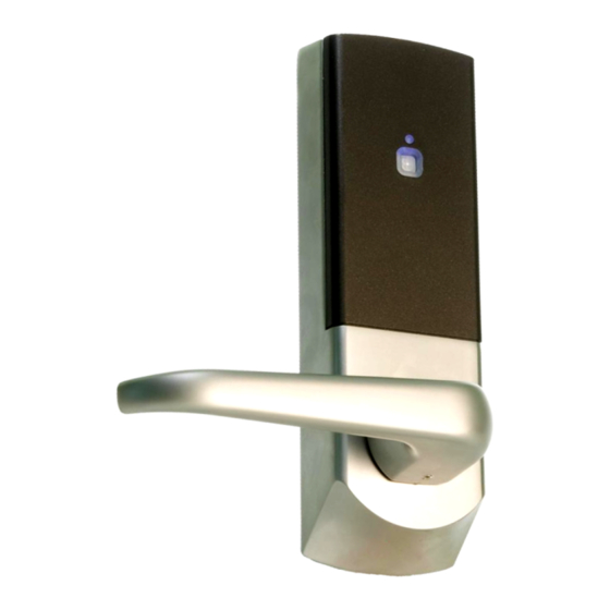
Ins-30056 Easyprox compact
Technical Support
+44 (0)1273 811011
Technical help is available:
Documentation on all Paxton Access products can be found on our web site - http://www.paxton.co.uk/
Layout
Parts list
1
5
Tools List
Power Drill
Drill bits 10mm, 25mm.
8mm spanner
2mm Allen key
Philips screwdriver
Hammer / mallet
Monday - Friday from 07:00 - 01:00 (GMT)
Saturday from 09:00 - 13:00 (GMT)
This unit is for Internal use only.
2
3
6
7
8
10
11
12
support@paxton.co.uk
1) Front Lock Assembly x1
2) Rubber Escutcheon x2
4
3) Rear Lock Handle x1
4) Ins-30067 - Easyprox Template
5) Handle x2
6) Square Drive x1
7) Strike Plate Backbox x1
9
8) Strike Plate x1
9) Battery Pack x1
10) Tubular Mortice Latch x1
11) Latch Screws x4
13
12) Short Fixing Screws x4
13) Long Fixing Screws x4
Chisel 25mm
Stanley knife
Adhesive tape, pencil, bradawl,
Tape measure
Hacksaw for cutting bolts
Advertisement

Related Manuals for Paxton Access Easyprox compact


Summary of Contents for Paxton Access Easyprox compact
- Page 1 Technical help is available: Monday - Friday from 07:00 - 01:00 (GMT) Saturday from 09:00 - 13:00 (GMT) Documentation on all Paxton Access products can be found on our web site - http://www.paxton.co.uk/ Layout This unit is for Internal use only.
- Page 2 Fitting the latch Step 1 Decide on the height of the door latch from the floor and mark a height line on the edge and about 80mm across both faces of the door. Fold the template along one of the dotted lines (right or left side) and tape it to the door with the latch centre line positioned on the height mark.
- Page 3 Step 10 Fit the battery pack into the unit. Replace the access plate and secure with the standoff screws. Step 11 Fit the rubber escutcheons to front plate and the back plate. Present the front and rear lock assembly to the door, locating the square drive in its recess and secure the two parts of the lock together with the fixing screws.
- Page 4 Normal Operation - LED Indications The inside handle is permanently engaged with the latch. The external handle is free to move and is only engaged once access has been granted. Presenting a valid user card to the unit will cause the Green LED to flash briefly and the handle will then engage (default 4 seconds).
-
Page 5: Silent Operation
Door open time (seconds) 1. Take the door open time function card from the starter pack. 2. Present the card to the reader. The reader will start beeping. 3. Wait for the required period you wish the door to remain open. 4. -
Page 6: Battery Replacement
3. Remove the access plate to reveal the battery pack. - Fig 2 4. Unplug the lead and replace the pack with a new Paxton Access battery pack. - Fig 3. (NOTE: The unit will retain its settings and should not be manually reset) 5.