
Subscribe to Our Youtube Channel
Summary of Contents for Woodward UMT 1
- Page 1 37139C UMT 1 Measuring Transducer Manual Version 1.9xx / 2.0xx / 2.1xx / 3.0xx / 3.1xx Manual 37139C...
- Page 2 Provides other helpful information that does not fall under the warning or caution categories. Woodward reserves the right to update any portion of this publication at any time. Information provided by Woodward is believed to be correct and reliable. However, Woodward assumes no responsibility unless otherwise expressly undertaken.
-
Page 3: Table Of Contents
The information in this publication is no longer current, and may not reflect changes or safety issues that have occurred since the publication was originally released. Refer to the UMT 1 Packages manual 37356 for more recent information about the UMT 1 unit. Contents 1. - Page 4 Manual 37139C UMT 1 - Measuring Transducer 6. C ....................23 HAPTER ONFIGURATION Basic Data.............................. Configuration Access ..........................24 Sealing (Until Version 1.9xx) ....................... 24 Password (Starting with Version 2.0xx / 3.0xx) ................26 Change Passwords (Starting with Version 2.0xx / 3.0xx) ............27 Measurement ............................
- Page 5 Manual 37139C UMT 1 - Measuring Transducer Illustrations and Tables Illustrations Figure 3-1: Wiring diagram 100/400 V version .......................... 8 Figure 3-2: Wiring diagram 690 V version ..........................9 Figure 3-3: Power supply ................................10 Figure 3-4: Measuring inputs - voltage 100/400 V versions ..................... 11 Figure 3-5: Measuring inputs - voltage, 690 V version ......................
-
Page 6: Chapter 1. General Information
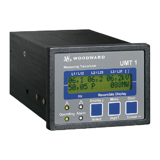
Introduction ≡≡≡≡≡≡≡≡≡≡≡≡≡≡≡≡≡≡≡≡≡≡≡≡≡ The UMT 1 is a measuring transducer for true RMS values. The UMT 1 can measure an electrical three-phase system with current and voltage measuring inputs. The primary measured values are calculated and displayed on the two-line, 16 character LC Display, and also transmitted by either analog outputs (configurable as -20 to 20 mA, 0 to 20 mA, or 4 to 20 mA) or a communication interface to a higher level-control system. -
Page 7: Chapter 2. Electrostatic Discharge Awareness
CAUTION To prevent damage to electronic components caused by improper handling, read and observe the pre- cautions in Woodward manual 82715, Guide for Handling and Protection of Electronic Controls, Printed Circuit Boards, and Modules. © Woodward Page 7/62... -
Page 8: Chapter 3. Installation
This is where the direct 0 Vdc parameterizing cable DPC must be plugged in. C (kWh impulse) E (open collector) Subject to technical modifications. 2004-02-26 | UMT 1 Wiring Diagram u1ww-0904-ap.skf Figure 3-1: Wiring diagram 100/400 V version Page 8/62 © Woodward... -
Page 9: Wiring Diagram 690 V Version
DPC must be plugged in. C (kWh impulse) E (open collector) Subject to technical modifications. 2004-11-16 | UMT 1 Wiring Diagram u1ww-1110-ap.skf 2004-11-16 | UMT 1 Wiring Diagram u1ww-1110-ap.skf Figure 3-2: Wiring diagram 690 V version © Woodward... -
Page 10: Power Supply (Standard / Option N)
Manual 37139C UMT 1 - Measuring Transducer WARNING All technical data and ratings indicated in this chapter are not definite! Only the values indicated under Technical Data on page 42 are valid! CAUTION A circuit breaker must be located near to the unit and in a position easily accessible to the operator. -
Page 11: Measuring Inputs
Manual 37139C UMT 1 - Measuring Transducer Measuring Inputs ≡≡≡≡≡≡≡≡≡≡≡≡≡≡≡≡≡≡≡≡≡≡≡≡≡ NOTE The various distribution systems (w-system) must be taken into account when configuring the moni- toring devices. Refer to “Measuring Systems” on page 29 for a description of these systems. -
Page 12: Currrent
Manual 37139C UMT 1 - Measuring Transducer Currrent WARNING Before disconnecting the secondary terminals of the transformer or the connection of the transformer at the control unit ensure that the transformer is short-circuited. NOTE Current transformers are secondary and should be connected to ground single-sided. -
Page 13: Outputs
Manual 37139C UMT 1 - Measuring Transducer Outputs ≡≡≡≡≡≡≡≡≡≡≡≡≡≡≡≡≡≡≡≡≡≡≡≡≡ Analog Outputs (Options A1 to Analog output Analog output Figure 3-8: Analog outputs Description 0 to 20 / 4 to 20 / -20 to +20 mA Analog output 1 Option A2/3/6 1.5 mm²... -
Page 14: Interface (Options Su)
Manual 37139C UMT 1 - Measuring Transducer Interface (Options ≡≡≡≡≡≡≡≡≡≡≡≡≡≡≡≡≡≡≡≡≡≡≡≡≡ A B C D E A B C D A B C Figure 3-10: Interfaces Terminal Description A (X1) B (X2) C (X3) D (X4) E (X5) RS-232 RS-422 RS-485, Modbus RTU Slave... -
Page 15: Chapter 4. Functional Description
Manual 37139C UMT 1 - Measuring Transducer Chapter 4. Functional Description Direction of Power ≡≡≡≡≡≡≡≡≡≡≡≡≡≡≡≡≡≡≡≡≡≡≡≡≡ In the event that the current transformers of the unit are wired according to the wiring picture below, the following values are displayed: Positive generator active power •... -
Page 16: Power Factor Definition
Manual 37139C UMT 1 - Measuring Transducer Power Factor Definition ≡≡≡≡≡≡≡≡≡≡≡≡≡≡≡≡≡≡≡≡≡≡≡≡≡ The phasor diagram is used from the generator's view. This defines the following definitions. Power Factor is defined as a ratio of the real power to apparent power. In a purely resistive circuit, the voltage and current waveforms are instep resulting in a ratio or power factor of 1.00 (often referred to as unity). - Page 17 Manual 37139C UMT 1 - Measuring Transducer Phasor diagram: inductive capacitive © Woodward Page 17/62...
-
Page 18: Chapter 5. Display And Operating Elements
Manual 37139C UMT 1 - Measuring Transducer Chapter 5. Display and Operating Elements The pressure-sensitive membrane of the front panel consists of a plastic coating. All keys have been designed as touch-sensitive membrane switch elements. The display is a LC-display, consisting of 2 rows of 16 characters each, with indirect green lighting. -
Page 19: Leds
Manual 37139C UMT 1 - Measuring Transducer LEDs ≡≡≡≡≡≡≡≡≡≡≡≡≡≡≡≡≡≡≡≡≡≡≡≡≡ NOTE If neither of the "Wye" and "Delta" LEDs is illuminated, the first line of the display indicates the wire current values. "Wye" Indication of the wye voltages Color: Yellow If this LED is illuminated, the values indicated on the display are the wye (star) voltages (phase-neutral). -
Page 20: Push-Buttons
Manual 37139C UMT 1 - Measuring Transducer Push-Buttons ≡≡≡≡≡≡≡≡≡≡≡≡≡≡≡≡≡≡≡≡≡≡≡≡≡ In order to facilitate the setting of the parameters the buttons are equipped with an "AUTOSCROLL" function while the controller is in the configuration mode. It permits the user to rapidly advance to the next setting and configuration screens, the digits, or the cursor position. -
Page 21: Lc-Display
Manual 37139C UMT 1 - Measuring Transducer LC-Display ≡≡≡≡≡≡≡≡≡≡≡≡≡≡≡≡≡≡≡≡≡≡≡≡≡ LC Display LC display Performance values can be monitored from the two-line display, provided that the control is in automatic mode. In configuration mode, the individual parameters are displayed. Display in Automatic Mode (First Line of the Display: Measured Values) NOTE The user can scroll through the first display line with the button "Display ↓". -
Page 22: Display In Automatic Mode (Second Line Of The Display: Measured Values)
Manual 37139C UMT 1 - Measuring Transducer Display in Automatic Mode (Second Line of the Display: Measured Values) NOTE The "Menu" button may be used to scroll through the messages shown on the second line of the dis- play. Display in automatic mode, second line: Measuring Values ---------------- 00.00 xxxxxxxxxx... -
Page 23: Chapter 6. Configuration
Manual 37139C UMT 1 - Measuring Transducer Chapter 6. Configuration Configuration can be done via the front panel push buttons and the front panel LC display. CAUTION Please note that configuration only should be done while the system is not in operation. -
Page 24: Basic Data
Manual 37139C UMT 1 - Measuring Transducer Basic Data ≡≡≡≡≡≡≡≡≡≡≡≡≡≡≡≡≡≡≡≡≡≡≡≡≡ Software version Software version X.xxxx This screen displays the software version loaded into the control (the last two xx are for software revisions which do not affect the function of the unit). - Page 25 Manual 37139C UMT 1 - Measuring Transducer Code for seal 001 (new entry) 00000 to 60000 Code no. 000 New code: ????? After breaking the old seal, the unit requests the code number for the new seal. Seal- ing can now be effected with a new code number.
-
Page 26: Password (Starting With Version 2.0Xx / 3.0Xx)
Manual 37139C UMT 1 - Measuring Transducer Password (Starting with Version 2.0xx / 3.0xx) The unit is equipped with a three-level code and configuration hierarchy, which allows different user access to the control. A distinction is made between: Code level CS0 (User Level) Factory password = none This code level allows for monitoring of the system and does not permit access to the parameters. -
Page 27: Change Passwords (Starting With Version 2.0Xx / 3.0Xx)
Manual 37139C UMT 1 - Measuring Transducer Change Passwords (Starting with Version 2.0xx / 3.0xx) NOTE Once the code level is set, it will not be changed even after entering the configuration repeatedly an incorrect code number has been entered, the code level is set to CS0, thus locking the device for ex- ternal persons. -
Page 28: Measurement
Manual 37139C UMT 1 - Measuring Transducer Measurement ≡≡≡≡≡≡≡≡≡≡≡≡≡≡≡≡≡≡≡≡≡≡≡≡≡ WARNING The following values must be entered correctly for the generator to be monitored. Failure to do so may lead to incorrect measuring of parameters resulting in damage to or destruction of the generator and/or personal injury or death. -
Page 29: Measuring System
Manual 37139C UMT 1 - Measuring Transducer Measuring System ≡≡≡≡≡≡≡≡≡≡≡≡≡≡≡≡≡≡≡≡≡≡≡≡≡ NOTE The measuring transformer must be connected in accordance with the measuring system. Refer to Measuring Systems on page 38 Measuring system 1W, 1W4, 1W3, 2W3, 2W4 Connection type Select the measuring configuration to be utilized by the control unit. For a descrip-... -
Page 30: Screens For "+Kwh" And "-Kwh" Setting
Manual 37139C UMT 1 - Measuring Transducer Screens for "+kWh" and "-kWh" Setting Counter pulse to measure the real energy positive/negative Pulse/kWh logic negative The output of the kWh pulse (inductive as well as capacitive) may occur both nega- tive (per kWh pulse the Open Collector output [terminal 60/61] is opened) and posi- tive (per kWh pulse the Open Collector output [terminal 60/61] is closed). -
Page 31: Display Refresh Time
Manual 37139C UMT 1 - Measuring Transducer Display Refresh Time NOTE From version 2.1xx the refresh rate of the display (cycle time) can be adjusted. Refresh time display 1 to 5 s Refresh time Display This parameter determines how often the display is updated/refreshed. This parame- ter only affects the display. -
Page 32: Analog Outputs (Options A1/2/3/4/6/8)
Manual 37139C UMT 1 - Measuring Transducer Analog Outputs (Options A1/2/3/4/6/8) ≡≡≡≡≡≡≡≡≡≡≡≡≡≡≡≡≡≡≡≡≡≡≡≡≡ It is possible to apply a certain measuring quantity (according to the table below) to each available analog output via the push buttons. At the -20/0/4 to 20 mA analog outputs, the signal may be transmitted as a –20 to 20 mA, a 0 to 20 mA, or a 4 to 20 mA value. - Page 33 Manual 37139C UMT 1 - Measuring Transducer Example: analog output 2 (-10/0 to 10 V: terminals 50/52, -20/0/4 to 20 mA: terminals 52/53) Output of the phase-phase voltage L12: Output range of the (20 mA) -20 to +20 / 0 to 20 / 4 to 20 mA / OFF...
-
Page 34: Interface (Option Su)
Manual 37139C UMT 1 - Measuring Transducer Interface (Option ≡≡≡≡≡≡≡≡≡≡≡≡≡≡≡≡≡≡≡≡≡≡≡≡≡ Screens for Protocol DK3964 (Option Data block RK512 0 to 255 Data block RK512 Data block address in receiver (i.e. PLC). Data word RK512 0 to 255 Data word RK512 Data word address in receiver (i.e. -
Page 35: Screens For Protocol Can Bus (Options Su/Sb)
Manual 37139C UMT 1 - Measuring Transducer Screens for Protocol CAN Bus (Options SU/SB) NOTE Please note that IDs must not be allocated twice. This applies to all units linked to the bus system. Moreover, all IDs adjusted at the unit must be set to different values. -
Page 36: Chapter 7. Commissioning
Manual 37139C UMT 1 - Measuring Transducer Chapter 7. Commissioning DANGER - HIGH VOLTAGE When commissioning the control, please observe all safety rules that apply to the handling of live equipment. Ensure that you know how to provide first aid in the event of an uncontrolled release of energy and that you know where the first aid kit and the nearest telephone are. - Page 37 Manual 37139C UMT 1 - Measuring Transducer Now, proceed as follows to change the code level: until version 1.9xx: Sealing function Coding Enter: "ON" select and confirm using the "Select" button Code input Code no. 000 Code? ????? Enter: Button "Select".
-
Page 38: Appendix A. Measuring Systems
UMT 1 - Measuring Transducer Appendix A. Measuring Systems CAUTION The grounding of the N-wire in the voltage measurement must not be done at the UMT 1, but must be done at a central location (PEN-System). Measuring System 1W ≡≡≡≡≡≡≡≡≡≡≡≡≡≡≡≡≡≡≡≡≡≡≡≡≡... -
Page 39: Measuring System 1W4
Manual 37139C UMT 1 - Measuring Transducer Measuring System 1W4 ≡≡≡≡≡≡≡≡≡≡≡≡≡≡≡≡≡≡≡≡≡≡≡≡≡ Three-phase mains • 4-wire (wye) system (P = √3 × V × I × cosϕ) • Symmetrical (balanced) load • Voltage measurement in L1, L2 and L3 • Current measurement in L1 •... -
Page 40: Measuring System 2W3
Manual 37139C UMT 1 - Measuring Transducer Measuring System 2W3 ≡≡≡≡≡≡≡≡≡≡≡≡≡≡≡≡≡≡≡≡≡≡≡≡≡ Three-phase mains • 3-wire (delta) system • Asymmetrical (unbalanced) load • Voltage measurement in L1, L2 and L3 • Current measurement in L1 and L3 (open delta connection) • Grounding of the neutral point (connected transformer terminals) -
Page 41: Appendix B. Dimensions
Manual 37139C UMT 1 - Measuring Transducer Appendix B. Dimensions Front view Back plate mounting optional (please order brackets P/N 8923-1023) Bottom view Back view with connecting terminals 2005-08-30 / UMT 1 Abmessungen u1ww-3505-ab.skf Figure 7-6: Dimensions © Woodward Page 41/62... -
Page 42: Appendix C. Technical Data
Manual 37139C UMT 1 - Measuring Transducer Appendix C. Technical Data Voltage measuring --------------------------------------------------------------------------------------------- - Measuring voltage Rated value (V ) /∆ .......... [1] 66/115 Vac rated [4] 230/400 Vac [7] 398/690 Vac Maximum value V (UL/cUL) ........[1] max. 150 Vac ph-ph [4] max. - Page 43 Manual 37139C UMT 1 - Measuring Transducer Interface ----------------------------------------------------------------------------------------------- isolated - Insulation voltage ............. dependent on model: 500 to 1,500 Vdc - Version ........................variable Housing ---------------------------------------------------------------------------------------------------------- - Type .................... APRANORM DIN 43 700 - Dimensions (B × H × T) ................96 × 72 × 130 mm - Front cutout (B×H) ..............
-
Page 44: Appendix D. Measured Quantities And Accuracy
Manual 37139C UMT 1 - Measuring Transducer Appendix D. Measured Quantities and Accuracy Measuring value Display/range Accuracy Note Frequency 40.0 to .80.0 Hz 0.05 Hz Voltage 0 to 520 V / 0 to 65 kV 0.5 % Accuracy depending on the... -
Page 45: Appendix E. Interface Telegram
Manual 37139C UMT 1 - Measuring Transducer Appendix E. Interface Telegram Communication Interface Addresses ≡≡≡≡≡≡≡≡≡≡≡≡≡≡≡≡≡≡≡≡≡≡≡≡≡ Number Content (words) Unit Remark Modbus Profibus Telegram header "305" Telegram type (02, 03) Voltage L12 (04, 05) Voltage L23 (06, 07) Voltage L31 (08, 09) - Page 46 Manual 37139C UMT 1 - Measuring Transducer Number Content (words) Unit Remark Modbus Profibus Internal Bit 15 = 1 \ (44, 45) Internal Bit 14 = 0 / Bit 13 = 1 \ Internal Bit 12 = 0 / Bit 11 = 1 \...
- Page 47 Manual 37139C UMT 1 - Measuring Transducer Number Content (words) Unit Remark Modbus Profibus Internal Bit 15 = 1 \ (50, 51) Internal Bit 14 = 0 / Bit 13 = 1 \ Internal Bit 12 = 0 / Bit 11 = 1 \...
-
Page 48: Description Of The Data Format
Manual 37139C UMT 1 - Measuring Transducer Description of the Data Format ≡≡≡≡≡≡≡≡≡≡≡≡≡≡≡≡≡≡≡≡≡≡≡≡≡ NOTE Certain addresses have two parts, the measured value and the exponent multiplier! Voltage and current 0 to 9.999 without sign measured in [V, A] Real power 0 to 9.999 with sign (+/-) -
Page 49: Examples
Manual 37139C UMT 1 - Measuring Transducer Examples = 103, Exponent = 2 103 x 10 [V] = 1,030 [V] = 10.3 kV = 80, Exponent = -1 80 x 10 [A] = 8.0 [A] = 8.0 A = 123, Exponent = 4 123 x 10 [W] = 1,230,000 [W] = 1.23 MW... -
Page 50: Framework Data For The Interfaces
Manual 37139C UMT 1 - Measuring Transducer Framework Data for the Interfaces ≡≡≡≡≡≡≡≡≡≡≡≡≡≡≡≡≡≡≡≡≡≡≡≡≡ Framework Data to Procedure 3964 (TTY, RS-232, RS-485) String length ......8 bit Stop bit........ 1 bit Parity bit ......1 bit with even parity Idle state ......This corresponds to the state log. "1" (20 mA with TTY) Data format ...... -
Page 51: Framework Data For Can Bus
Manual 37139C UMT 1 - Measuring Transducer Framework Data for CAN Bus Transmitting protocol ..CAN (CiA) Hardware ......CAN bus Transmission rate ....adjustable Special characteristic ...Bt0 = 03, Bt1 = 1C Every 200 ms a data telegram of 8 bytes is sent, which is structured as follows (all word variables are in the high... -
Page 52: Framework Data For Profibus Dp
Manual 37139C UMT 1 - Measuring Transducer Framework Data for Profibus DP Receiving Range Byte 0 and the following ..Telegram according to description Example: ......No. 1 - Byte 0/1 = telegram header "302" No. 2 - Byte 2/3 = voltage L12 No. -
Page 53: Appendix F. List Of Parameters
Manual 37139C UMT 1 - Measuring Transducer Appendix F. List of Parameters Product number P/N _____________________________ Rev _______________________________ Version UMT 1 _______________________________________________________________ Project _____________________________________________________________________ Serial number S/N _______________ Date ______________________________ Setting range Parameter Default setting Customer setting Option 100/400/690 V... - Page 54 Manual 37139C UMT 1 - Measuring Transducer Setting range Parameter Default setting Customer setting Option 100/400/690 V ANALOG OUTPUT CONFIGURATION Analog output 1 A2/3/6 OFF OFF A1/4/8 -20 to +20mA -/+20mA -/+20mA -20 to.+20mA 0 to 20 mA ...
- Page 55 Manual 37139C UMT 1 - Measuring Transducer Setting range Parameter Default setting Customer setting Option 100/400/690 V ANALOG OUTPUT CONFIGURATION Analog output 6 A6/8 OFF OFF -20 to +20mA -/+20mA -/+20mA -20 to.+20mA 0 to 20 mA ...
-
Page 56: Table 7-1: Analog Outputs, Table Of Values
Manual 37139C UMT 1 - Measuring Transducer Value Lower and upper setting value 0 V, -10 V 10 V, 20 mA 0 mA, 4 mA, -20 mA U L1-N 0 to 65,000 V U L2-N 0 to 65,000 V U L3-N... -
Page 57: Appendix G. Service Options
≡≡≡≡≡≡≡≡≡≡≡≡≡≡≡≡≡≡≡≡≡≡≡≡≡ If a control (or any part of an electronic control) is to be returned to Woodward for repair, please contact Wood- ward in advance to obtain a Return Authorization Number. When shipping the unit(s), attach a tag with the fol- lowing information: •... -
Page 58: Packing A Control
Stuttgart [+49 (711) 789 54-0]. They will help expedite the processing of your order through our distributors or local service facility. To expedite the repair process, contact Woodward in advance to obtain a Return Authoriza- tion Number, and arrange for issue of a purchase order for the unit(s) to be repaired. No work can be started until a purchase order is received. -
Page 59: How To Contact Woodward
+49 (711) 789 54-100 e-mail: stgt-info@woodward.com For assistance outside Germany, call one of the following international Woodward facilities to obtain the address and phone number of the facility nearest your location where you will be able to get information and service. Facility... -
Page 60: Engineering Services
Colorado, or from one of many worldwide Woodward offices or authorized distributors. Field engineers are expe- rienced on both Woodward products as well as on much of the non-Woodward equipment with which our prod- ucts interface. For field service engineering assistance, please contact us via our toll-free or local phone numbers, e-mail us, or use our website and reference field service. -
Page 61: Technical Assistance
Manual 37139C UMT 1 - Measuring Transducer Technical Assistance ≡≡≡≡≡≡≡≡≡≡≡≡≡≡≡≡≡≡≡≡≡≡≡≡≡ If you need to telephone for technical assistance, you will need to provide the following information. Please write it down here before phoning: Contact Your company ____________________________________________________ Your name _______________________________________________________... - Page 62 Phone +49 (711) 789 54-0 • Fax +49 (711) 789 54-100 stgt-info@woodward.com Homepage http://www.woodward.com Woodward has company-owned plants, subsidiaries, and branches, as well as authorized distributors and other authorized service and sales facilities throughout the world. Complete address/phone/fax/e-mail information for all locations is available on our website (www.woodward.com).
Need help?
Do you have a question about the UMT 1 and is the answer not in the manual?
Questions and answers