Table of Contents
Advertisement
Quick Links
Advertisement
Table of Contents

Summary of Contents for Abra CNC ENGRAVER 01
- Page 1 ABRA CNC ENGRAVER ABRA CNC ENGRAVER...
- Page 2 [This page is left intentionally blank]...
-
Page 3: Table Of Contents
Table of Contents BILL OF MATERIALS ............................4 INTRODUCTION ............................. 5 1-ABRA CNC MACHINE ..........................6 1.1-SAFETY CONSIDERATIONS ........................6 1.2-MATERIALS REQUIRED ........................7 1.3-HARDWARE DESCRIPTION ........................7 2-ASSEMBLY INSTRUCTIONS ......................... 7 2.1-ELECTRICAL ASSEMBLY ........................8 2.1.1- CONTROLLER BOARD ........................8 2.1.3- MOTORS ............................ -
Page 4: Bill Of Materials
BILL OF MATERIALS USB to Mini USB CNC Controller Zip Ties 240mm V-Slot Railing 220mm V-Slot Cable Board Railing x4 200mm V-Slot M8x218mm Lead M8x238mm Lead Screw Rod M8x260mm Smooth M8x240mm Railing x2 Screw Rod Rod x2 Smooth Rod x2 2020 Corner Aluminum Motor M5\M3\M2.5\M2\M1.5Allen... -
Page 5: Introduction
USB. This kit is ideal for hobbyists interested in rapid prototyping and manufacturing. The CNC is a 3-axis removal machine. This ABRA Kit includes all the necessary equipment and instructions to be ready for operation within a few hours. -
Page 6: 1-Abra Cnc Machine
1-ABRA CNC MACHINE 1.1-SAFETY CONSIDERATIONS The use of this machine may pose many safety risks that must be addressed: Always wear the appropriate eye protection, breathing mask and ear protection needed for each job. Always inspect the CNC machine for any visible problems before each operation. It ... -
Page 7: Materials Required
1.2-MATERIALS REQUIRED This kit comes with everything you need to get the CNC machine functioning. You must have a computer capable of supporting the Candle, GCAM and Arduino software. Tools Suggested for Assembly: Precision ruler or caliper Marker Test board for calibrating Mill. -
Page 8: Electrical Assembly
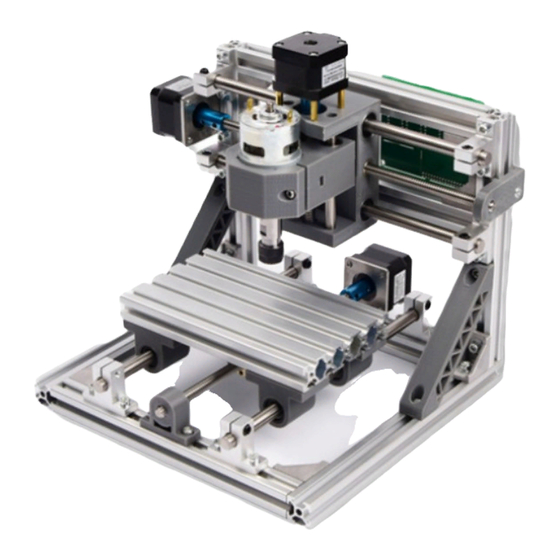
2.1-ELECTRICAL ASSEMBLY Z-AXIS X-AXIS Y-AXIS Figure 1- Electrical Assembly 2.1.1- CONTROLLER BOARD The controller board is where all the hardware is connected. The power and programmer cables are connected as well as the motors and drivers. Connection is done as shown below in Figure 3. -
Page 9: 3- Motors
(Note: We observed the maximum voltage the motor and controller board can take is 36VDC. We also noted as the voltage supplied to the motor is not constant and alternates causing reduction in performance. To fix this issue we suggest to solder a capacitor at the spindle motor. We provide the capacitor in the kit, if you wish to improve the quality of your mill, you will be required to solder them, and polarity is not of concern, since the capacitor is bi-polar.) 2.1.3- MOTORS... -
Page 10: 3-Grbl Controller Software
Machine. We recommend using a desktop computer with USB 2.0 port if possible. 3.1-INSTALLATION Several different software options are offered for running the CNC machine. The ABRA Kit uses Candle. Different users prefer different versions. Usually the code is open- sourced and is updated frequently. -
Page 11: Firmware Loading
Arduino software (IDE). There are Three methods to programming the board. Target Link: https://abra-electronics.com/3d-printers-en/cnc-machines/cnc-kit-01-cnc- engraving-machine-kit.html Visit the target link suggested above, and click on Attachments to download getting- started.zip Method 1: ... -
Page 12: Setup And Testing
3.3-SETUP AND TESTING In this section, we establish connection with the GRBL Controller software host. We must connect on the appropriate port and set the correct Baud rate. Baud Rate: 115200 If the motors, board and power supply have been installed we can connect the unit and test the system. -
Page 13: 1- Candle
3.3.1- CANDLE Figure 4 - Candle port connection (Note: If you cannot connect and have the same status message as shown in figure 4 under console section. Close any software that is communicating with the board such as Arduino or any other CNC software.) - Page 14 Figure 5- Candle Unlock (Note: Alarm lock will only occur if you use Hard limits and print in the console the warning message. To reset you use this button or type $X in the window and press the paper airplane to send to the controller.)
- Page 15 Figure 6- Motor Movement (Note: Jog allows movements, if we press up the table should move outwards and inwards for the bottom button. Left and right will move left and right respectively. The white button will move the z-axis up or down respectively. Movements are done in mm and are set so accordingly to the firmware settings.
- Page 16 Figure 7- Zeroing before Milling (Note: Both buttons in one rectangular box are used for zeroing Z-axis and XY-axis. This button is important as you must zero the machine coordinate before every mill project you want to send. Home feature can be used once the coordinates are zeroed to return back to that zeroed point.
- Page 17 Figure 8- Spindle Speed and Enable (Note: By clicking on the three lines you can expand options for the spindle and set the speed to 10000 for a speed of 7000 RPM. By clicking on the spiral icon, you can activate the drill motor and it should start spinning.
-
Page 18: 4-Setup And Calibration
4-SETUP AND CALIBRATION Your CNC machine is almost ready to use. At this stage, we should have the entire frame assembled, the power properly connected, established connection to the GRBL software and control of each motor axis. This step will show us how to fine tune the machine for precise milling. - Page 19 Using GRBL Control- Axis Control Menu, move the X and Y motors to their minimum position (0 position). Move the Z axis to its minimum position. Click “Zero Position” (or “Zero XY” and “Zero Z”). This command has stored these positions as zero in the machine’s EEPROM.
-
Page 20: Calibrating Motor Steps
4.1.2 CALIBRATING MOTOR STEPS This step is crucial for a precise milling. This tuning ensures that the motors travel the exact distance they are commanded. Repeat this procedure for each X,Y and Z axis motor: Send motor to its zero position. ... -
Page 21: Gcam Svg To G-Code
5.2- GCAM SVG to G-CODE This section is designed to simply show you how to convert SVG into NC for you CNC Machine. Download the SVG image you wish to mill. If you have a PNG or JPEG, they must be converted into SVG as SVG is a vector image that has coordinates for each line. -
Page 22: File Upload (Candle)
5.3- FILE UPLOAD (CANDLE) Figure 10- GRBL 3.0 File Upload 5.4- AXIS CONFIGURATION Once the design file has been converted and loaded, we attach the material to the plate for milling. For best results, try to centre the material on the plate. ... - Page 23 Figure 11- GRBL 3.0 File Send It is a good idea to perform a “dry run” before starting your mill. Set the Z Axis and spindle higher so that it hovers above the board without touching it. Then start the mill and observe if any part of the job goes out of bounds. (Note: Try using your mouse by right-clicking and drag on the window where the object is shown, you will notice the depth and layers to milling an object.)
Need help?
Do you have a question about the CNC ENGRAVER 01 and is the answer not in the manual?
Questions and answers