Table of Contents
Advertisement
Quick Links
SPB2WDI48524
Instruction Manual
Attach here the label
Appliquer l'étiquette ici
SIN 255.255.255/999.999
Write here the location
Ecrivez ici l'emplacement
A
B
C
E
D
-50°C to +85°C
-40°C to +50°C
(-58°F to 185°F)
(-40°F to 122°F)
I P20
IP50
MANUAL SBP2WDI48524 code 15-029-669 - 131218
ENGLISH
Read carefully the instruction manual. If the instrument is used in a manner not specified by the producer, the
protection provided by the instrument may be impaired.
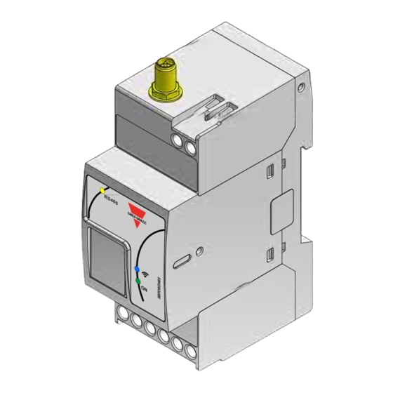
PRODUCT DESCRIPTION
Part
Description
A
Antenna connection terminal
Power supply terminals A1(+), A2(-):
24 VDC (±20%), 20 mA, CL.2
B
The display is powered through the SBP2WDI48524 and the internal connection can max handle 5.5 A.
Be sure to use correct power supply.
Indication LEDs:
Green
ON
Power supply ON
(ON)
OFF
Power supply OFF
Short blink
Sending data when associated to a SH2WBU230N.
C
Blue
Long blink
Sending data when not associated to any SH2WBU230N or when receiving a network configuration.
(WiDup)
ON
During network configuration when configured as a router.
ON
Communication OK on the RS485 bus
Yellow
OFF
No communication is present on the RS485 bus (Timeout)
(RS485)
Blink
Communication error (Wrong connection)
Display connection terminals (see picture pag.2):
Pin number
Connection terminal
Display wires color
1
+24 V
Brown
2
B (+)
Yellow
D
3
A (-)
Green
4
GND
White
Max one display can be connected.
E
2.4 GHz Antenna with 2 meters cable
Approvals: CE, cULus according to UL60950.
UL notes:
• This product is intended to be supplied by a Listed Information Technology Equipment AC Adaptor marked
NEC Class 2 or LPS.
• Max ambient temperature: 40°C
http://www.carlogavazzi.com/
FRANÇAIS
Lire attentivement le manuel de l'utilisateur. Si l'appareil est utilisé dans des conditions différentes de celles
spécifiées par le fabricant, le niveau de protection prévu par l'instrument peut être compromis.
DESCRIPTION DU PRODUIT
Partie
Description
A
Terminal de connexion d'antenne
Bornes d'alimentation A1(+), A2(-):
24 VCC (±20%), 20 mA, CL.2
B
L'afficheur est alimenté par l'interface SBP2WDI48524 ; la connexion interne peut gérer 5,5 A maximum.
Veiller à utiliser l'alimentation correcte.
LED d'informations:
Verte
ON
Alimenté.
(ON)
OFF
Alimentation coupée.
Clignotement court
Envoi de données quand associé à un SH2WBU230N.
C
Bleue
Clignotement long
Envoi de données associé à aucun SH2WBU230N ou lors de réception d'une configuration.
(WiDup)
ON
Pendant la configuration s'il est configuré comme un routeur.
ON
Communication sur le bus RS485 correcte
Jaune
OFF
Pas de communication sur le bus RS485 (Timeout)
(RS485)
Clignotement
Erreur de communication (Erreur de connexion)
Bornes de connexion de l'afficheur (voir illustration à la page 2)
Num. du broche
Borne de connexion
Couleur des fils de l'afficheur
1
+24 V
Marron
2
B (+)
Jaune
D
3
A (-)
Vert
4
GND
Blanc
Un seul afficheur peut être connecté.
D
Antenne 2,4 GHz avec câble de 2 mètres
Homologations: CE, cULus selon UL60950.
Notes UL:
• Ce produit est conçu pour être alimenté par un adaptateur secteur Listés comme équipements de technologie
de l'information NEC Classe 2 ou LPS.
• Température ambiante maxi: 40°C
CARLO GAVAZZI
Advertisement
Table of Contents

Summary of Contents for CARLO GAVAZZI SPB2WDI48524
- Page 1 SPB2WDI48524 ENGLISH FRANÇAIS Read carefully the instruction manual. If the instrument is used in a manner not specified by the producer, the Lire attentivement le manuel de l’utilisateur. Si l’appareil est utilisé dans des conditions différentes de celles Instruction Manual protection provided by the instrument may be impaired.
- Page 2 This device complies with FCC radiation exposure limits for an uncontrolled environment. This device shall be installed and operated with a minimum distance of 20 cm between users or by- standers and the device. MANUAL SBP2WDI48524 code 15-029-669 - 131218 http://www.carlogavazzi.com/ CARLO GAVAZZI...
Need help?
Do you have a question about the SPB2WDI48524 and is the answer not in the manual?
Questions and answers