Advertisement
Quick Links
Advertisement

Summary of Contents for ICAS UWI-IQ
- Page 1 UWI-IQ manual ( rev. 5.07.2019) Page 1/12...
- Page 2 UWI-IQ Universal wireless interface in the band 868 MHz Universal wireless link UWI-IQ to UWI-IQ D R A F T UWI-IQ manual (rev. 5.07.2019) Page 2/12...
-
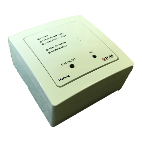
Page 3: Terminal Description
There are wide possibilities of user configurations available, which allows to adapt the UWI-IQ to specific user application. The UWI-IQ can be tested by the TEST button. It is possible to test the The configuration is designed as wireless and user friendly special PC... - Page 4 UWI-IQ application. Set/check the configurable parameters of all UWI-IQ in installation /system. 6. Choose the best place to fix the UWI-IQ unit with regards to an easy connection with the source of the input signal and/or the receiver of relay / Loop output signals and power supply source.
- Page 5 Input delay If an input delay is set, and the UWI-IQ input level is changed from normal to active level, the alarm/fault message is not sent immediately , but only if the active level is kept during the pre-alarm / pre-fault indication period. The running pre-alarm period is indicated by flashes of correspondent LED (Red/Yellow) every delay step.
- Page 6 Test Press the test button shortly (till red led TEST gets on) - the UWI-IQ gets into the test mode, red LED indicates Test and the message 'T' is sent to other nodes. As soon as the other UWI-IQ in the wireless link or other UWI-IQ and CHOR-IQ detectors into the wireless system receive this message they will get into the test mode too.
- Page 7 E message (before Fault output activation) it serves for indication of start up time and manual reset acceptation it can serve optionally also for indication of any local internal UWI-IQ fault Red LED ( REMOTE ALARM)
-
Page 8: Factory Reset
(TEST / RESET) button - User friendly Push-button operation The UWI-IQ is trying to estimate the user intention and if the UWI-IQ is in other status than normal a simple short press and release of the detector button can be the first easy solution of the most UWI-IQ/loop situation like TEST indication, HUSH indication or a remote alarm/fault indication etc. -
Page 9: Technical Specification
Transmission of two input signals from one UWI-IQ by wireless to two relay outputs and loop option of the second UWI-IQ unit, which is configured into the wireless link (peer to peer) or to uCU-IQ system by compatible communication protocol and messages. -
Page 10: Watch-Dog Reset
Reset: By the push button from the Test mode or by the message 'r' It clears the UWI-IQ indications and status words – the local alarm, local fault, remote alarm, remote error (Reset can by applied even in local alarm /fault condition, but the Interface will indicate... - Page 11 SPI message structure and instruction set (the same structure and instruction set is used for both ICAS wireless system or OEM system) SPI message structure: // CMD // PTYPE // DATA_1 // DATA_2 // DATA_3 // DATA_4 // CRC// where = F0 ..
- Page 12 ======================================================================================================== Notice : (The resistor 3k9 EOL+ is not necessary more) The switch at the position J3 on the terminal board allows to choose between IFC and IMC control panels and the loop current is switched to a correspondent standby level automatically at the same time.)
Need help?
Do you have a question about the UWI-IQ and is the answer not in the manual?
Questions and answers