Table of Contents
Advertisement
Available languages
Available languages
Quick Links
Advertisement
Table of Contents

Subscribe to Our Youtube Channel
Related Manuals for PROEL INCOM


Summary of Contents for PROEL INCOM
- Page 1 INCOM sistema interfonico per sportelli Glass counter interphone...
-
Page 3: Table Of Contents
INDICE 1. PRECAUZIONI D’USO 2. DESCRIZIONE 3. FUNZIONI E CONTROLLI 4. DOTAZIONE 5. VISTA FRONTALE 6. PANNELLO POSTERIORE 7. INSTALLAZIONE ED ALIMENTAZIONE 8. ISTRUZIONI OPERATIVE - UTILIZZO DELL’ INTERFONO MODALITÀ DI FUNZIONAMENTO FUNZIONE DEI TASTI 9. ISTRUZIONI PER L’ INSTALLAZIONE – CONNESSIONI E TARATURE POSIZIONAMENTO DEL MICROFONO LATO CLIENTE POSIZIONAMENTO DELL’... -
Page 4: Precauzioni D'uso
1. PRECAUZIONI D’USO AVVERTENZA : Per ridurre il rischio di folgorazione, non rimuovere il coperchio (o il pannello posteriore). All’interno non sono contenute parti riparabili dall’utente; affidare la riparazione a personale qualificato. ATTENZIONE : Per ridurre il rischio d’incendio o di folgorazione, non esporre questo apparecchio alla pioggia o all’umidità. - Page 5 Messa a terra o polarizzazione: • Si devono prendere precauzioni in modo tale che la messa a terra e la polarizzazione dell’ apparecchio non siano pregiudicate. • Le parti metalliche dell’apparecchiatura sono collegate a massa tramite il cavo d’alimentazione. • Se la presa utilizzata per alimentazione non possiede collegamento a massa, rivolgersi ad un elettricista qualificato per fare collegare l’apparato a massa tramite il terminale.
- Page 6 GARANZIE E RESI: Il sistema interfonico INCOM è provvisto della garanzia di funzionamento e di conformità alle proprie specifiche, come dichiarate dal costruttore. La garanzia è di 24 mesi dalla data di acquisto. I difetti rilevati entro il periodo di...
-
Page 7: Descrizione
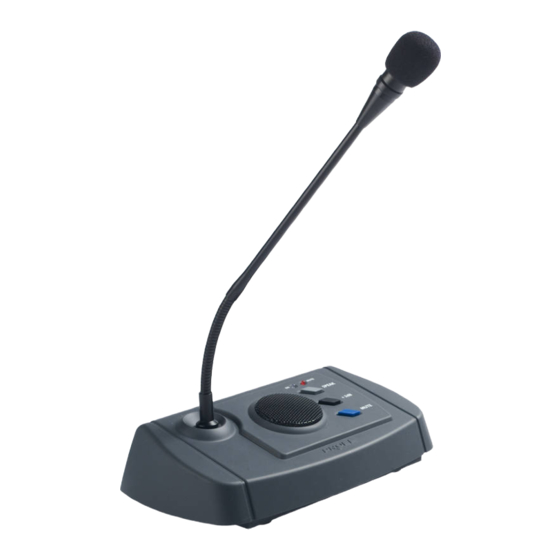
2. DESCRIZIONE L’INCOM è un sistema ideato per agevolare la comunicazione tra operatore e pubblico attraverso il vetro di sicurezza di uno sportello. Tramite questo interfono l’intera conversazione può svolgersi in modo estremamente naturale e senza necessità di effettuare commutazioni forzate, disimpegnando il personale di sportello da queste fuorvianti attività. -
Page 8: Pannello Posteriore
6. PANNELLO POSTERIORE fig.2 6 Connettore per alimentatore CA esterno. 7 Uscita audio a livello Linea per registrazione. 8 Uscita audio a livello linea per collegamento ad amplificatore esterno. 9 Connessione Jack 3,5 mm per microfono esterno. 10 Connessione plug RCA per altoparlante esterno. 11 Taratura livello di intervento del dispositivo VOX (ducking). -
Page 9: Funzione Dei Tasti
8.2 FUNZIONE DEI TASTI • Tasto PRIORITY Questo tasto permette all’ Operatore di forzare la propria comunicazione verso l’utente disattivando automaticamente il microfono applicato esterno. In questo caso il canale dell’ Operatore è attivo mentre quello del cliente viene disattivato, funzione utile nel caso l’... -
Page 10: Posizionamento Della Base Interfonica
Regolare infine i trimmer 12 e 13 in modo da garantire un livello di volume sufficiente sia per l’operatore che per il cliente, prestando comunque molta attenzione a non avvicinarsi alla condizione critica del rientro acustico (larsen). CARATTERISTICHE TECNICHE MODEL INCOM Auxiliary output: 500mV/600ohm REC output: 500mV/600ohm S/N Ratio: >... -
Page 11: Schema A Blocchi Di Funzionamento
INOP PRIORITY COMP THRESHOLD VOX OUT REC. OUT LINEA BUFFER La Proel SpA persegue una politica di costante ricerca e sviluppo, di consegueza si riserva il diritto di apportare modifi- che ai prodotti esistenti, senza preavviso. REV: 00 / 02-08... - Page 13 INDEX 1. IMPORTANT SAFETY INSTRUCTIONS 2. DESCRIPTION 3. FUNCTIONS AND CONTROL 4. STANDARD INCOM PACKAGE 5. FRONT VIEW 6. REAR PANEL 7. INSTALLATION AND POWER SUPPLY 8. OPERATING MODE INSTRUCTIONS- INTERPHONE USE 9. INSTALLATION INSTRUCTIONS- CONNECTIONS AND ADJUSTMENTS TECHNICAL CHARACTERISTICS...
- Page 14 1.IMPORTANT SAFETY INSTRUCTIONS CAUTION: To reduce the risk of electric shock do not remove cover (or back panel). No user serviceable parts inside. Refer servicing to qualified personnel only. WARNING:To reduce the risk of fire or electric shock, do not expose this apparatus to rain or moisture. This symbol is intended to alert the user of the presence of uninsulated dangerous voltage within the product enclosure that may be of sufficient magnitude to constitute a risk of electric shock to persons.
- Page 15 Grounding or Polarization: • All precautions must be observed in order to avoid grounding or polarization defeating. • Unit metal parts are grounded through the AC power cord. • If the AC power outlet doesn’t have grounding, consult an electrician for outlet grounding. Power cord protection: The power cord should be routed in a way it will not be walked on or pinched by items placed upon or against it, paying particular attention to cords at plugs, convenience receptacles and wall outlet.
- Page 16 Are to be considered out of warranty all those defects due to an improper use or tampering acts. PROEL S.P.A. is not responsible for any damage that occurs due to a wrong unit installation.
- Page 17 • +3dB key control to double temporarily sound power for customer speaker side. • ANTILARSEN device • LINE High Level signal output to allow INCOM system to be used as a simple microphone call stand. • LINE High level signal output for current conversation between the operator and the customer recording purposes.
- Page 18 6. REAR PANEL fig.2 6 External AC power supply connector 7 Line level Audio output for recording purposes 8 Line Level Audio Output for external amplifiers connection purposes 9 3,5 mm Jack Connection for external microphone 10 RCA plug connection for external loudspeakers 11 VOX intervention level adjustment device ( duk king).
- Page 19 When there is no Public address system such PA CALL key is not used. When INCOM unit is powered on , the system is set automatically on full-duplex operating mode, for such operating mode both customer/operator audio channels are active; The customer and operator can communicate alternatively throughout a normal oral information exchange.
- Page 20 12 and 13. Key 11 corresponds to the trimmer for VOX intervention adjustment level INCOM system is supplied by the producer with standard factory adjustments. If necessary during the installation further adjustments can be carried to ensure the best performance and acoustic system efficiency .
- Page 21 PRIORITY COMP THRESHOLD VOX OUT REC. OUT LINEA BUFFER Proel SpA pursue a policy of continuous research and development. Proel SpA reserve the right to modify product circuitry and appearance at any moment, without prior notice. REV: 00 / 02-08...
Need help?
Do you have a question about the INCOM and is the answer not in the manual?
Questions and answers