Table of Contents
Advertisement
Quick Links
Advertisement
Table of Contents

Related Manuals for In Win IW-RS248-03


Summary of Contents for In Win IW-RS248-03
- Page 1 IW-RS248-03 User Manual...
-
Page 2: Table Of Contents
Table of Contents PREFACE ............................. 1 SAFETY INFORMATION ....................... 1 CAUTION ............................ 2 SPECIFICATIONS .......................... 3 Product Introduction ......................4 Box Contents ....................... 4 General Information ....................5 1.2.1 Front Panel Controls and Indicators ................. 6 1.2.2 Rear Panel Configuration ....................7 Hardware Installation ...................... - Page 3 Expander Board Introduction .................... 22 Compatibility Lists ......................23 Q&A ..........................23 Technical Support ......................24...
-
Page 4: Preface
InWin’s server website to download the latest updated version. SAFETY INFORMATION To ensure a safe and smooth operation of your InWin IW-RS248-03, it is essential that you choose an appropriate location for the system, provide an appropriate operating environment and supply an adequate amount power for all components of the system. -
Page 5: Caution
Electrostatic discharge (ESD) and ESD protection: In most cases, ESD may damage disk drives, electronic boards and other parts. We recommend that you conduct installation only at an ESD free space. If not possible, perform ESD protection protocol by wearing an anti-static wrist straps attached to the ground on any unpainted metal surface on your server during operation. -
Page 6: Specifications
SPECIFICATIONS RS248-03 Model Name EIA-RS310D Standard ATX (12“ x 9.6”), CEB(12” x10.5”), EEB(12” x 13”) M/B Form Factor Dimensions (D x W x H) 660mm x 482.6mm x 87mm (26” x 19” x 3.5”) w/o Front Door External : Hot-swap 2.5” SSD/HDD (7mm) x 48 (U.2 NVMe x 8) Drive Bay Rear hot-swap 2.5”SSD/HDD (7mm) x 2 Supports... -
Page 7: Product Introduction
1 Product Introduction Box Contents When you open the carton box of IW-RS248-03, the contents should include:... -
Page 8: General Information
General Information When you open the chassis, it should reflect the diagram’s image Rear top cover Middle top cover CRPS Redundant module power supply ATX or CEB & EEB Motherboard 48 x 2.5” 7mm PWM Fan (Max. 4pcs) tool-less HDD trays Front Controls and indicators... -
Page 9: Front Panel Controls And Indicators
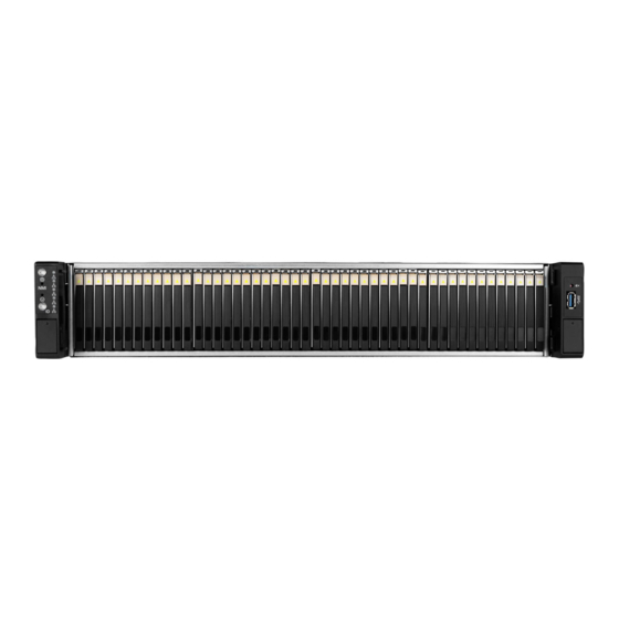
1.2.1 Front Panel Controls and Indicators IW-RS248-03 supports SAS/SATA 48 x 2.5”(7mm) disk bays, or SAS/SATA 40 x 2.5”(7mm) with NVMe 8 x 2.5”(7mm) disk bays in specific location, and the control panel, USB IO ports and indicators on the handles. -
Page 10: Rear Panel Configuration
The slot supports low profile cards. The bracket should 7 Low Profile PCI-E Slot be removed before using. This slot is for In Win OS disk backup module (option), OS HDD which supports two 2.5” 7mm SSDs and features hot-swap function. -
Page 11: Hardware Installation
2 Hardware Installation Removing and Installing a Hard Drive IW-RS248-03 is featured 2.5” 7mm tool-less trays. Users no longer need to use screws to mount disks, and can swap drives faster. 2.1.1 Installing a Hard Drive Step 1: Press the release button then pull outward on the handle. -
Page 12: Removing A Hard Drive
Step 3 Step 4 Push back Insert 2.1.2 Removing a Hard Drive Step 1: Press the release button then pull outward on the handle. Step 2: Release and pull the tray handle outward. Take out the 2.5'' (7mm) hard drive from the tray, and then push the tray handle back. Step 3: Insert the HDD tray to the slot. -
Page 13: Removing And Inserting The Top Cover
Step 3 Step 4 Push back Insert Removing and Inserting the Top Cover Step 1: Loosen the screw and press inward the button then lift the middle top cover up. Step 2: Loosen the screws of the rear top cover on the both sides, pull back the cover and lift to remove. - Page 14 Step 2 Step 3 Step 4...
-
Page 15: Removing And Installing The Fan Module
Removing and Installing the Fan Module IW-RS248-03’s built-in fan modules feature a tool-less design, which makes it easy to maintain. 2.3.1 Removing the Fan Module Step 1 : Hold and pull out the fan module from the fan slot. Step 1 Pull 2.3.2 Installing the Fan Module... -
Page 16: Removing And Installing The Psu Module
Removing and Installing the PSU Module The IW-RS248-03 built-in a redundant power supply with two power supply units. With this function, the system is capable of still functioning if one of the modules fail. To replace it, the user only needs to release the failed module, then insert a functional module. -
Page 17: Installing Slide Rail
2. The two PSU modules’ output wattage must be the same. nstalling Slide Rail The IW-RS248-03 is a rackmount model, which support EIA-RS310D standard cabinets and chassis racks. InWin provides standard slide rails to let users mount the chassis on to the cabinets. -
Page 18: Attach The Inner Rail To The Chassis
Step 3 Step 1 ~ 2 2.5.3 Attach the Inner Rail to the Chassis Step 1: Align the chassis sidewall standoffs to the inner rail keyholes. Slide the inner rail toward the front until the standoff snaps into place, securing the rail to the chassis. -
Page 19: Mount The Rail Bracket To The Cabinet
2.5.4 Mount the Rail Bracket to the Cabinet Step 1: Extend the rail bracket over the rear rack of the cabinet. Step 2: Pull out the rear hook on the end of the outer rail, align and push the rail bracket pins into the post holes on the rack. -
Page 20: Insert The Chassis To The Cabinet
2.5.5 Insert the Chassis to the Cabinet Step 1: Pull out the middle rail to the stop position. Step 2: Move the ball bearing retainer to the front end of the middle rail, it should click into the locked position. Step 3: Insert the inner rails of the chassis into the middle rails on the both sides of the rack. -
Page 21: Installing The Motherboard
Installing the Motherboard Before installing the motherboard, please find the IO shield from your motherboard package, and install it into the system IO window (Refer to 1.2.2). If you cannot find the IO shield, please check with your motherboard vendor, or contact InWin for IO shield OEM service. -
Page 22: Connecting Led, Front Control Panel And Front Usb
2.7.2 Connecting LED, front control panel and front USB Refer to your motherboard user guide for pin functions and locations, then plug the connectors to the pins on the motherboard to activate the functions. USB 3.0 LED Connector... -
Page 23: Backplane Introduction
Connector Name Abbreviation Color Front IO Indication CONN2 Power LED PW LED WHITE/BLACK Power ON/OFF Button with LED CONN3 Alarm LED SYS LED WHITE/GREY System Fail LED CONN4 ID LED ID LED WHITE/BROWN Chassis ID Button with LED CONN5 LAN 1 LED LAN1 LED WHITE/RED LAN LED... - Page 24 Bottom Side SlimLine Backplane Top Side Bottom Side...
- Page 25 Print Location Description ICE1 For MCU FW Programming MODE_SEL VPP over 12C Protocol Selection (for future use) 4 Expander Board Introduction Print Location Description M/S SEL For future use MUTE_BUTTON Button for muting alarm SYS_ERR_LED LED indicator for Fan fails or over temperature MB_FAN For connecting to Motherboard Fan connector TEST...
- Page 26 Does backplane supports 6Gb SAS? A: InWin IW-RS248-03 is accommodated with 12Gb SAS backplane by default. And also supports 6Gb SAS drive. c. Does the chassis support 3.5”, 2.5”, SAS and SATA drive? Can I mix the different type of drives in an enclosure? A: InWin IW-RS248-03 supports 2.5”...
- Page 27 g. Do I need a RAID controller card to connect the backplane? A: If you would like to construct a solid hardware RAID system, it is required. However, whether to use the RAID controller card or not depends on your purpose and budget. We recommend discussing with InWin’s channel partner for their suggestions.
Need help?
Do you have a question about the IW-RS248-03 and is the answer not in the manual?
Questions and answers