Table of Contents
Advertisement
Quick Links
Advertisement
Table of Contents

Related Manuals for Metronic DL7 Series

Summary of Contents for Metronic DL7 Series
- Page 1 DL7, DL7L MULTICHANNEL ELECTRONIC DATA LOGGER USER’S MANUAL Version: 180228EN...
- Page 2 DL7, DL7L Before installation, carefully read all the instructions, especially those concerned with safety. The recorder has been manufactured according to the requirements of relevant EU directives. These instructions must be stored in a safe place near the installation of the steam flow computer at all times.
-
Page 3: Table Of Contents
DL7, DL7L TABLE OF CONTENTS MARKING AND DOCUMENTATION ................ 6 SAFETY INFORMATION ..................7 EQUIPMENT DELIVERY, HANDLING AND STORAGE ........10 Basic components ........................10 Storage ............................10 Accessories ..........................10 KEY INFORMATION ABOUT THE DEVICE............11 Intended use ..........................11 Basic functions .......................... - Page 4 DL7, DL7L Port Ethernet ..........................33 DISPLAY STRUCTURE AND MAIN FUNCTION KEYS ......... 34 Face plate ..........................34 9.1.1 Title strip ..........................34 9.1.2 Side menu ..........................35 9.1.3 Main screen .......................... 36 9.1.4 USB Port ..........................36 Screen keyboard ........................36 FIRST START UP AND KEY ACTIVITIE ............
- Page 5 DL7, DL7L 14.3.4 Totalizers ......................... 58 14.4 Communication settings ......................58 14.4.1 PORT ETHERNET ......................58 14.4.2 Port RS-485........................59 14.5 Screen settings .......................... 59 14.5.1 Tables ..........................59 14.5.2 Trends ..........................60 ARCHIVE ....................... 61 15.1 How to initiate, restart and stop recording ................. 61 15.2 Archive settings .........................
-
Page 6: Marking And Documentation
DL7, DL7L 1 MARKING AND DOCUMENTATION Equipment protected throughout by double insulation or reinforced insulation. Functional earth (ground) terminal, to enable the product to function correctly. Not used to provide electrical safety. Caution, risk of electric shock. Caution, risk of danger, refer to accompanying documentation. Caution, Electrostatic Discharge (ESD) sensitive circuit. -
Page 7: Safety Information
Intended use Check that the product is suitable for use with the application. Determine the correct installation situation. Prior to installation Metronic AKP products should take into account any environmental limitations of devices, specified in the manual. - Page 8 Post 'warning notices' if necessary. Cleaning and maintenance Metronic AKP products require no maintenance beyond periodic battery replacement. Expected battery life is 10 years after the expiry of which must be returned to the manufacturer for a replacement.
- Page 9 Returning products Customers and stockists are reminded that under EC Health, Safety and Environment Law, when returning products to Metronic AKP they must provide information on any hazards and the precautions to be taken due to contamination residues or mechanical damage which may present a health, safety or environmental risk.
-
Page 10: Equipment Delivery, Handling And Storage
DL7, DL7L 3 EQUIPMENT DELIVERY, HANDLING AND STORAGE Prior to dispatch, each Metronic AKP device is inspected and calibrated to ensure efficient operation. CAUTION!! Upon receipt, each package should be inspected for any potential damage. The content of the package should also be checked and the actual number of elements should be compared against the manufacturer's list of items presented in the consecutive sub-section. -
Page 11: Key Information About The Device
DL7, DL7L 4 KEY INFORMATION ABOUT THE DEVICE 4.1 Intended use DL7s are versions of a multi-channel microprocessor-based measuring device with electronically recorded measurement results. The recorder is intended to measure process signals in industrial settings and may be used to measure temperature values and other physical quantities processed into a standard current signal 0/4-20mA, and in particular, humidity, pressure, flow, level and chemical composition, etc. -
Page 12: Device Versions
DL7, DL7L Results recording Measurement and calculation results as well as totalizer readings can be recorded in the recorder’s internal memory with the capacity of 2 GB. Data are saved as text files and protected with encoded checksum. Apart from the measured values, the recorder also saves events (power loss, resetting, exceeded threshold values, etc.) and authorised operations. -
Page 13: Device Configuration
DL7, DL7L 4.4 Device configuration A factory configuration code is stated on the name plate. DL7-A-B-C-D-E-F-G DL7L-A-B-C-D-E-F-G where: Mark Housing version For mounting in panels DL7L Freestanding In the place of each letter, a suitable module number should be provided as per the instructions given in the tables below: Number Mark... -
Page 14: Dl7 Modules
DL7, DL7L 5. DL7 MODULES Individual electrical connection diagrams are given in section ELECTRICAL INSTALLATION. 5.1 DL7 basic kit Each DL7 device is composed of the following: case face plate with an LCD display and USB port type A ... -
Page 15: The Input Module Measuring The Temperature And Voltage Mv Dl7-In6Tc
DL7, DL7L 5.6 The input module measuring the temperature and voltage mV DL7-IN6TC temperature measurements using thermometers (a complete list of sensors is given in the chapter discussing the technical data), compensation of the junction compensation - with a fixed value or a measurement using another channel ... -
Page 16: Digital Input Module (Modbus Rtu) Dl7-In2Rs485
DL7, DL7L 2 independent RS485 ports galvanically separated, each input has a separate four-pole terminal block, 24 VDC (max 200 mA) output for powering external transducers, a two-colour LED diode informing about the module's operating status. 5.11 Digital Input Module (Modbus RTU) DL7-IN2RS485 ... -
Page 17: Technical Data
DL7, DL7L 6. TECHNICAL DATA FRONT PANEL LCD TFT 7” 800 px X 480 px Type of display: LED lbacklight Reading field size: 152 mm X 91 mm Keyboard: resistive touch panel Indication: LED red/blue Port USB (front panel) USB 2.0 ( with limited functionality, for Version connection of FLASH storage) USB standard ‘A’... - Page 18 DL7, DL7L SUPPLY Supply voltage 24 VDC (18 .. 36 VDC) Maximum power consumption 48 W ( when installed seven modules ) The internal delay fuse 3.15 A, the exchange Security only by the service company ELECTRICAL CONNECTIONS (terminal connectors) Type screw terminal connectors wire 1.5 mm...
-
Page 19: Rtd Inputs Module Measuring The Temperature And The Resistance Dl7-In6Rtd (Dl7-In3Rtd)
DL7, DL7L Galvanic separation between channels None WARNING: In the DL7 device, it is posible to instal max 4 modules with power output 24V DC at the same time (DL7-IN6I (24V)). RTD inputs module measuring the temperature and the resistance DL7-IN6RTD (DL7-IN3RTD) Number of inputs ... -
Page 20: Voltage Input Module Dl7-In6V
DL7, DL7L Measuring range 0–20 mA; 4–20 mA; (the actual range -22 .. 22 mA) Resolution 0.001 mA = +25° C) < ±0.1% measuring range Measurement accuracy (T ( typically < ±0.05%) < ±0.02% /°C measuring range Temperature drift 12 ±10% Input resistance Input protection Polymer fuse 50 mA (resetable) - Page 21 DL7, DL7L Binary inputs module DL7-IN6D Number of inputs State Sensor type: frequency measurement 0.1 .. 1000 Hz Counting pulses (at frequencies 0 .. 100 Hz) Resolution measurement of frequency 0.1 Hz < ±0.01% measuring range Measuring range (measurement of frequency) ( typically <...
-
Page 22: Analogue Outputs Module Dl7-Out3
DL7, DL7L Maximum operating voltage / operating current 24 VAC / 0.5 A or 36 VDC / 0.5 A The maximum voltage allowed 42 VAC or 60 VDC Maximum peak current 1.5 A by 1 ms Galvanic separation from the other circuits 250 VAC;... - Page 23 DL7, DL7L -55° .. +175° C ±0.5° C KTY83 -67° .. +347° F ±0.9° F (NXP Rev06-4.04.2008) -40° .. +300° C ±0.8° C KTY84 -40° .. +572° F ±1.5° F (NXP Rev06-8.05.2008) 0 .. 4000 Ω (or sub-range) ±0.5 Ω (typ. ±0.3 Ω) Linear resistance Table thermocouples Sensor type...
-
Page 24: Mechanical Installation
DL7, DL7L 7 MECHANICAL INSTALLATION Prior to the commencement of any assembly work, please read carefully the information concerning safety described in section SAFETY INFORMATION DL7 is a panel-mounted device. It can be built into panels at least 1mm thick. Before installation, a 186 (+1.1) mm x 138 (+1) mm rectangular opening must be cut out in the panel. - Page 25 DL7, DL7L The recorder cannot be exposed to direct heat generated by other equipment. When assembled, the operating device cannot be affected by interference from other components (contacts, power relays, inverters)
-
Page 26: Electrical Installation
DL7, DL7L 8 ELECTRICAL INSTALLATION Before the commencement of any connection works, please read the safety information given in section SAFETY INFORMATION Connecting the supply voltage, measurement and control signals is possible due to detachable bolt connectors situated at the back plate of the device. Wires of cross-section area of up-to 1.5 mm2 may be connected to the terminal strips. -
Page 27: Galvanic Insulation In The Device
DL7, DL7L 8.1 Galvanic insulation in the device Fig. 8.2 Galvanic separation in DL7 (functional separation 500VAC @ 1min) 8.2 DL7 modules – connection diagrams Detailed information concerning individual modules is given in section MODULES. Fig. 8.3 Base module M – wiring diagram. Fig.8.4 DL7-IN6I module output transducer wiring diagram. - Page 28 DL7, DL7L passive transducers active transducers Fig. 8.5 DL7-IN6I(24V) module output transducer wiring diagram. Fig.8.6 RTD sensor wiring to DL7-IN6RTD module diagram. Fig.8.7 Thermocouple wiring to DL7-IN6TC module diagram.
- Page 29 DL7, DL7L Fig.8.8 Wiring diagram of transducers with -10V ÷ +10V voltage output to DL7-IN6V module. Fig. 8.9 Wiring diagram for DL7-IN3 module.
- Page 30 DL7, DL7L Fig.8.10 The correct way to wire a variety of sensors to DL7-IN3 module. Fig.8.11 The incorrect way to wire a variety of sensors to DL7-IN3 module. Fig. 8.12 Wiring diagram for DL7-IN6D module.
- Page 31 DL7, DL7L The module DL7-IN6D standard current limiting inputs is set at 3.6m. In special cases, there is a possibility to change the level of switching using the jumpers located on the module board inside the device. Other available value level switch with the corresponding configuration jumpers are given in the table below: I MAX 0.45mA...
- Page 32 DL7, DL7L Fig. 8.14 Wiring diagram for DL7-IN6D module. Fig.8.15 Wiring diagram of receivers to Relay Outputs of DL7-OUT6RL module. Fig. 8.16 Wiring diagram for DL7-OUT3 module. Connection diagrams to individual types of modules remain the same regardless of the number of channels handled by a particular measurement card.
-
Page 33: Power Connection
DL7, DL7L 8.3 Power connection The power adapter used with the device is capable of delivering stabilized and non- stabilized 24 DC voltage. It is recommended to supply the device using an insulated 50 W power source. To ensure safety, the recorder's supply must satisfy the conditions applicable to lower voltage sources SELV (Safety Extra Low- Voltage), supplied with the 24 V DC as per the IEC60950-1. -
Page 34: Display Structure And Main Function Keys
DL7, DL7L 9 DISPLAY STRUCTURE AND MAIN FUNCTION KEYS 9.1 Face plate A 7" touch LCD touch screen is built into the face plate of the device which is the basic tool of communication with the user. Fig. 9.1 Face plate. The display is divided into three main areas whose descriptions are given in the relevant chapters. -
Page 35: Side Menu
DL7, DL7L It displays pictograms whose descriptions are given below together with the references to individual sections where these issues are described in detail. Two of the icons displayed on the strip are additionally provided with certain functions. Manufacturer logo / function icon responsible for making screen shots (Print screen). -
Page 36: Main Screen
DL7, DL7L 9.1.3 Main screen The main screen is used to present the results of all the measurements, display all function windows and upload data. 9.1.4 USB Port The USB port socket located on the face plate of the device enables connecting an external mass storage device (a USB flash drive) to move data stored in the internal memory from the device to a PC. -
Page 37: First Start Up And Key Activitie
The second level of the authorised user. It enables viewing and modifications of the device settings and deleting the archive files. Service This level is accessible solely for the authorised technicians of Metronic AKP. Factory The level is accessible solely for the manufacturer. -
Page 38: Change Of Password
DL7, DL7L Access level Password User Administrator After the initial login, the passwords can be changed to other; the procedure is described in the sub-section. The password keyboard allows to use only small and block letters and special characters. It is not possible to use letters specific to a particular language. -
Page 39: Change Of The Language
DL7, DL7L Detailed information regarding programming of the individual settings is given in section PROGRAMMING SETTINGS (). 10.3 Change of the language To change the settings in the first step user should login as the Administrator and proceed as per the information presented in section Login. -
Page 40: Entity Launching The Product On European Union Market
DL7, DL7L 11 ENTITY LAUNCHING THE PRODUCT ON EUROPEAN UNION MARKET Manufacturer: METRONIC AKP s.c. 31-261 Kraków, ul. Wybickiego 7 Tel.: (+48) 12 633 08 73 www.metronic.pl Vendor:... -
Page 41: User Screens
DL7, DL7L 12 USER SCREENS 12.1 Information about the device This screen contains all the basic data concerning the device. Data concerning: device model, ID, serial number, firmware, IP address, COM (RS485) communication parameters and Modbus address. Fig. 12.1 Model screen - Device data. Additionally, this screen contains two function buttons: Opens up the screen with the information on the currently installed measurement plates. -
Page 42: Results Tables
DL7, DL7L Fig. 12.2 Hardware – Hardware configuration data window. 12.2 Results Tables Depending on the number of defined tables, the window contains from 1 to 6 independent tabs. Each of them contains a table made up from up to 15 fields in the 3x5 layout. -
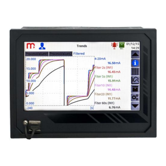
Page 43: Trends
DL7, DL7L 12.3 Trends Fig. 12.4 A model example of the Trends screen. Depending on the number of defined trends, the window contains from 1 to 6 independent tabs. Each tab contains the trend field, enabling the display of up to maximum 6 lines and the legend field containing information on the displayed values (channel description, current value and unit). -
Page 44: Archive
DL7, DL7L Fig. 12.5 Navigating from the Trend window to a Single Result Window. The User can switch the legend on and off by clicking the graph field. During the navigation between the individual tabs the legend display mode is not changed. The trends display last 360 s (with the legend switched off) or 240 s (with the legend switched on). -
Page 45: Main Menu
DL7, DL7L Fig. 12.6 Model Archive screen 12.5 Main menu This screen contains a menu made up from the functional icons and their descriptions. Fig. 12.7 Main menu screen. -
Page 46: Single Result Window
DL7, DL7L Clicking on the pictogram highlight a suitable sub-screen. Using the Main menu screen any changes to the device settings can be made. Having made and accepted the changes, click any icon on the side Menu. It will display a message requesting you to confirm the changes. Having approved them, the device will switch off and reboot with the new settings. -
Page 47: Alarms
DL7, DL7L The right part of the screen contains the trend value from the last 360 s. Clicking on the field outside the graph results in graph maximisation. Another clicking restores the normal view. Fig. 12.9 Clicking on the trend area in the single result window displays the graph in full screen mode. 12.7 Alarms Clicked on the alarm icon on the title bar displays the Alarms window. - Page 48 DL7, DL7L Fig. 12.10 Model Alarms screen. The grey colour means that the alarm for a particular channel has not been set. The white colour marks the set alarm. If an alarm is activated, a particular field is marked in one of the three colours (green, yellow, or red) selected by the user.
-
Page 49: Settings Of Calculation Channels
DL7, DL7L 13 SETTINGS OF CALCULATION CHANNELS In order to set the calculation channel, choose from the side menu the button , and then the channels icon . In the input tab, set the channel type: computed and enter the formula which the value will be calculated. The device allows to perform selected mathematical operations: addition, subtraction, division, multiplication, raising to the power of 2 and 3 and the square root. - Page 50 DL7, DL7L Fig. 13.1 Settings of calculation channels. Fig. 13.2 Entering the formula of the calculation channel. Calculation channels have the same functions that allow analysis as measurement channels: they can be displayed in the Result Tables window, in the Trends window and in single result...
-
Page 51: Programming Settings
DL7, DL7L 14 PROGRAMMING SETTINGS Having made any changes to the device setting, first confirm them using key in the right bottom part of the screen, and then using any icon on the Side menu. It will display a message requesting you to confirm the changes. -
Page 52: Date & Time
DL7, DL7L [1]: The slider enables setting the screen brightness level during the operation from 21 to 100%. [2]: It enables selection of the screen saver brightness level after the define idle time. User can choose two screen saver levels: 0% (the screen goes black) and 20%. [3]: The slider situated in this field enables setting the idle time after the elapse of which the screen goes black. - Page 53 DL7, DL7L DL7-IN6TC Mode: Disabled (Disabled, Enabled) Adjustment: [value] mV Compensation: Disabled (Disabled, Constant, Channel 1,..,100) [1]: It allows to switch the measurement input on or off. [2]: It enables an adjustment of the measurement result of the particular input by a positive or negative value given by the user.
- Page 54 DL7, DL7L [2]: It enables an adjustment of the measurement result of the particular input by a positive or negative value given by the user. [3]: The compensation method of thermocouple reference junction (cold junction compensation). Compensation can be provided by another measurement channel. In particular, a fixed value can be selected for compensation;...
-
Page 55: Channel Settings
DL7, DL7L [1]: Digital module measurement channel number . Each of the modules provides the user with 25 measuring channels, the numbering of which allows for easily assigning the appropriate measurement to the display channel. [2]: The number of the digital module port used. Each module has two active ports. [3]: Sensor or device Address from which the measurement results will be read. -
Page 56: General
DL7, DL7L Channel type: Demo(TEST) (Disabled, Measurement, Computed, Demo(TEST)) Characteristics: Linear (Linear, 1:1) [1]: The device enables assignment to the channel of one of four types: Off – the channel is not measured and displayed, Measurement enables assignment to the channel of a relevant output/input of a particular module, Computed- allows to enter the mathematical formula used for calculations, Demo(TEST) –... -
Page 57: Alarm
DL7, DL7L or by eliminating short pulses. The filter time constant should be customized to the maximum speed of changes in the measured process. [5]: It enables enabling or disabling the archiving of the results of the measurement of a particular channel. -
Page 58: Totalizers
DL7, DL7L [7]: Enabling the option switches on the archiving of the alarm and control thresholds exceeded alarm to the event file. [8]: The recording of measurement results can be controlled by means of exceeded alarm/control thresholds. Two different recording intervals can be set. The exceeded threshold can switch from MAIN ARCHIVE interval I to MAIN ARCHIWE interval II. -
Page 59: Port Rs-485
DL7, DL7L IP address: 192.168.0.10 Port: 502 Mask: 255.255.255.0 Gate: 192.168.0.1 Explanations: [1]: These parameters should correspond to the network where the recorder is intended to operate. [2]: It is recommended to use the 502 port dedicated to Modbus TCP. 14.4.2 Port RS-485 RS-485 port settings are essential if the device is to be connected to a PC. -
Page 60: Trends
DL7, DL7L 14.5.2 Trends In the upper part of the window, there is a drop down list from which you can select one of the six available options for programming. There is a window on the right side of the list where each item can be given any name not exceeding however 24 characters. -
Page 61: Archive
DL7, DL7L 15 ARCHIVE 15.1 How to initiate, restart and stop recording To start, resume or stop archiving, select the icon from the side menu. In the left bottom corner of the screen, there is a button which, depending on the current archiving status may start the archiving or stop it To create a new archive in first step stop the archiving process, and then press... -
Page 62: Erasing And Copying The Files To Usb Drive
DL7, DL7L XX- archive file number, numbering starts from 01 and ends at 99. In the event of exceeding 99, the numbering restarts from 01. YY - Device ID is consistent with the user settings, should the ID change, a new file will be created. - Page 63 DL7, DL7L Removing the pendrive before the writing process is complete may result in damaging of the recorded files. To erase a selected archive file, first select the required file from the list and then select the Delete selected file option.
-
Page 64: Additional Functions
DL7, DL7L 16 ADDITIONAL FUNCTIONS 16.1 Copying channel settings The device enables copying the settings assigned to a particular measurement channel and pasting them into another channel. It allows to accelerate the programming when there are channels to be programmed using the same settings. After pasting, change the address of the measurement input. -
Page 65: Changing The Background Color
DL7, DL7L selection will be confirmed by marking the name in blue. Then, from the menu on the left side select the Save selected on USB option. 16.4 Changing the background color To change the background color of the screen, you must press the description of the channel's title strip. - Page 66 DL7, DL7L Files are downloaded by clicking on the name attributed to each archive. Fig. 16.3 Web server view. In addition, the web server allows to view the measurement data collected in the result tables. To refresh the data, press Refresh button. Fig.
-
Page 67: Failure Symbols
DL7, DL7L 17 FAILURE SYMBOLS Emergency situation related to a particular channel are marked with a relevant symbol on the display: -------- Channel switched off, the symbol is displayed in the trend and collective tables window, for the switched off channels the single result window is not displayed. -
Page 68: Dl7L - Free-Standing Version
DL7, DL7L 18 DL7L – FREE-STANDING VERSION The device in a free-standing version has the same features as the version for panel mounting. Fig 18.1 DL7L face plate. In addition, the DL7L is equipped with special housing feet enabling convenient use of the device on the desk. - Page 69 DL7, DL7L To power the device, you can also use an external power supply such as eg. pulse power supply companies MEAN WELL available as an option in our offer. Fig 18.3 External power supply available as an accessory.
-
Page 70: Modbus Rtu / Modbus Tcp Transmission Protocol
DL7, DL7L 19 MODBUS RTU / MODBUS TCP TRANSMISSION PROTOCOL 19.1 Insights The device utilises the following Modbus functions: 03 (0x03) Read Holding Registers, 04 (0x04) Read Input Registes, In compliance with the Modbus RTU standard, the frame (information sent) is in the form Start Address Function... -
Page 71: Map Of Registers For Reading Current Results And Counters
DL7, DL7L 19.3 Map of Registers for Reading Current Results and Counters Current results are available in the floating-point format as per IEEE-754 for the 64-bit digit type with the floating point and single precision (64-bit floating point single). The counters are available in the floating-point format as per IEEE-754 for the 64-bit digit type with the floating point and double precision (64-bit floating point double).
Need help?
Do you have a question about the DL7 Series and is the answer not in the manual?
Questions and answers