Advertisement
Quick Links
Advertisement

Subscribe to Our Youtube Channel
Summary of Contents for CASTLE 110
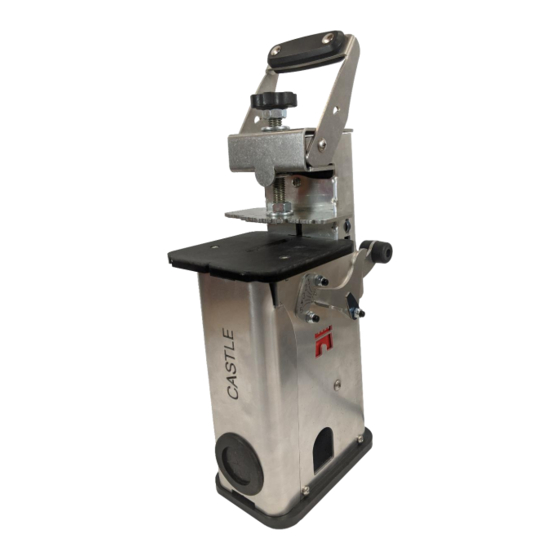
- Page 1 The CASTLE 110 Owner’s Manual Castle Inc., Petaluma California...
-
Page 2: Machine Safety
California factory. Upon receipt of the machine, inspect for shipping damage or missing parts. Report any damage IMMEDIATELY to the shipping company and to Castle, Inc. DO NOT attempt to operate the machine if you observe any physical damage. Contact Castle, Inc. at 800.282.8338 for instructions. - Page 3 Page 3 of 32 The Castle-110 OWNER’S MANUAL V1 CASTLE, INC. Page of 28 UAL V1...
- Page 4 Table of Contents 1 MACHINE SAFETY 2 INTRODUCTION 3 THE CASTLE 3 DEGREE SYSTEM 4 PACKAGING LIST 5 INSTRUCTIONS FOR USE 6 POSITIONING THE POCKETS 7 VACUUM PORT 8 CLAMPING TO A WORK BENCH 9 MACHINE ADJUSTMENTS SING THE TOCK...
- Page 5 The exclusive 3-degree screw angle minimizes the problem of component shifting (misalignment caused by tightening the screw) that is commonly associated with pocket joinery. With the Castle 110, it is now possible to create the same fully machined Castle Professional Pocket used by cabinetmakers in your own workshop or on the jobsite.
- Page 6 Below are samples of applications for Castle screw pockets. WARNING Read all safety warnings and instructions. Failure to follow all instructions in this manual may result in electric shock, fire and/or serious injury. Page 6 of 32 The Castle-110 OWNER’S MANUAL V1 CASTLE, INC.
- Page 7 3 The Castle 3 Degree System The Castle 110 has been designed to produce pockets joints with a 3-degree angle that virtually eliminates shifting and misalignment while assembling your work. The Castle 3-degree system requires the use of “Cheese” head pocket holes screws with a Torx drive head.
-
Page 8: Packing List
4 Packing List Within your Castle-110 shipment, you should receive the following: THE CASTLE-110 PORTABLE POCKET MACHINE PACKING LIST Part # Part Description A00110 The Castle-110 S90110 The Castle-110 Operator Manual with Warranty Activation Card B06964 5/32” Drill Bit, 6”... - Page 9 Optional accessories for the Castle 110: THE CASTLE-110 Optional Accessories Part # Part Description C11060 Work Stop Set, includes stop bar, left and right work stops B02517 Roughing Cutter for cutting in hardwoods The Castle-110 OWNER’S MANUAL V1 CASTLE, INC.
- Page 10 Figure 5a 2. Place the clamp lever in the stock thickness adjustment position. The half-moon cutout on the clamp lever will align with the top of the 110 as shown in figure 5b. Figure 5b 3. Turn the stock thickness adjustment knob clockwise until the clamping plate firmly touches the workpiece.
- Page 11 Feed the bit at a moderate rate. Soft stock generally requires a faster feed rate than harder materials. CASTLE, INC. The Castle-110 OWNER’S MANUAL V1 Page 11 of 32...
- Page 12 The pocket is now complete and ready for assembly. Caution: Always wear safety goggles and hearing protection when operating power tools. CASTLE, INC. The Castle-110 OWNER’S MANUAL V1 Page 12 of 32...
- Page 13 Note that precise pocket spacing is not critical for a strong joint if these general guidelines are followed. Your Castle 110 provides several methods to accurately locate the pockets. The clamping plate has a centerline and inch scale which can be used to position the pockets freehand, or the centerline or inch scale can be aligned with pencil marks to indicate where the pockets should be located.
- Page 14 (Figure 6c). Note that when the 110 is inverted, the pocket will be cut on the top surface of the workpiece.
-
Page 15: Vacuum Port
When possible, Castle recommends using a dust extraction vacuum to keep the tool free of chips and dust. The Castle 110 includes a vacuum port that is sized to fit most modern shop vacs and universal shop vacuum hose adapters. Select the dust extraction hose adapter that will work with your system. - Page 16 (Fasteners not provided) Additional Operating Instructions - Stationary vs. Freehand Your Castle 110 has been designed for maximum efficiency and can be operated in two modes: Stationary or Freehand. In the Stationary mode, the tool is clamped or screwed firmly to a work surface and the stock is clamped in place on the work deck.
-
Page 17: Machine Adjustments
5/8 inch stock, an overlay plate is provided. Simply push the clear plate onto the work deck of the Castle 110 as shown in figure 9a. Follow the instructions in section 6 for setting the clamp pressure and cutting the pocket. - Page 18 • Before making any adjustments, please sure that the machine is disconnected from the electrical power outlet. 1. Unplug the Castle 110. Remove the vacuum cover from the front of the Castle 110 by placing a finger inside the vacuum port and firmly pull away from the main housing.
- Page 19 Figure 9d CAUTION- Router bits are extremely sharp and if handled improperly may result in personal injury. Page 19 of 32 The Castle-110 OWNER’S MANUAL V1 CASTLE, INC. Page of 28 UAL V1...
- Page 20 Readjust if needed, repeating steps 3-7 above. Note: To prevent damage to the tool, NEVER tighten the collet without a bit inserted. Page 20 of 32 The Castle-110 OWNER’S MANUAL V1 CASTLE, INC. Page of 28 UAL V1...
- Page 21 When the web is set correctly, the threads of the screw will protrude past the end of the work to fully engage the part to be joined. Page 21 of 32 The Castle-110 OWNER’S MANUAL V1 CASTLE, INC. Page of 28...
- Page 22 Pilot Hole Height Adjustment The Castle 110 comes with the pilot hole drill guide bushing preadjusted at the factory and should not require readjustment. If the drill guide is no longer producing pilot holes in the center of the pocket, please call Castle at 800-282-8338 for information on how to adjust the drill guide properly.
- Page 23 1. Insert the stop bar into the stop bar port in either side of the Castle 110 with the notch facing down. The stop bar will lock into place when the notch engages the bottom of the stop bar port. (Figure 10a) Figure 10a 2.
-
Page 24: General Safety Rules
Because the motor is enclosed, it is important that the guidelines provided in this instruction manual are strictly observed. • The motor is serviced by Castle and if service is required please contact the factory. • Use dust extraction for clearing sawdust out of your machine case and creating air flow through the case to aid in cooling the motor. - Page 25 Water entering a power and footwear will further enhance your will increase the risk of electric shock. personal safety. Page 25 of 32 The Castle-110 OWNER’S MANUAL V1 CASTLE, INC. Page of 28 UAL V1...
- Page 26 Use of your finger on the switch or plugging in these devices can reduce dust-related power tools that have the switch on hazards. invites accidents. Page 26 of 32 The Castle-110 OWNER’S MANUAL V1 CASTLE, INC. Page of 28 UAL V1...
- Page 27 Always make sure the work piece is Power tools are dangerous in the hands free from nails and other foreign of untrained users. Page 27 of 32 The Castle-110 OWNER’S MANUAL V1 CASTLE, INC. Page of 28 UAL V1...
- Page 28 • Lead from lead-based paints, is very important and it relates to the • Crystalline silica from bricks Page 28 of 32 The Castle-110 OWNER’S MANUAL V1 CASTLE, INC. Page of 28 UAL V1...
- Page 29 We recommend that all tool service be performed by Castle, Inc. CLEANING WARNING To avoid accidents always disconnect the tool from the power supply before cleaning or performing any maintenance.
-
Page 30: Warranty Information
Castle, Inc. uses only the highest quality stocks available for the construction of our machines. The Castle 110 is warranted for one (1) full year from the date of purchase against workmanship or stock defects under normal use and service. Castle, Inc. is not responsible for failures or injuries due to negligence, misuse, alteration, unauthorized service, or accidents. - Page 31 Castle warrants the router motor for one (1) year from date of purchase. We recommend that you keep your bill of sale and 110 serial numbers. You will need this information for verification should there be any issues covered by the machine or motor warranty.
- Page 32 Castle, Inc. · 1364 North McDowell Blvd · Ste 1 · Petaluma · CA ·94954 1.800.282.8338 · www.castleusa.com Page 32 of 32 The Castle-110 OWNER’S MANUAL V1 CASTLE, INC. Page of 28 UAL V1...
Need help?
Do you have a question about the 110 and is the answer not in the manual?
Questions and answers