
Related Manuals for EYC DST01

Summary of Contents for EYC DST01
- Page 1 Operation-Manual eYc DST01 Universal Isolation Signal Converter / Splitter eYc DST01...
- Page 2 DST01 Signal / Meter DST01 Universal Isolation Signal Converter / Splitter Warning Symbol This document contains notices that you should observe to ensure your own personal safety, as well as to protect the product and connected equipment. These notices are highlighted in the manual by a warning triangle and are marked as follows.
-
Page 3: Table Of Contents
DST01 Signal / Meter DST01 Universal Isolation Signal Converter / Splitter Table of Contents 1. Introduction ..................Introduction ..................Features ..................... Programming Port ................Display Board Keys ................Menu Flowchart .................. Parameter Availability Table ............... 2. Installation and Wiring ............... 15 Unpacking .................. -
Page 4: Introduction
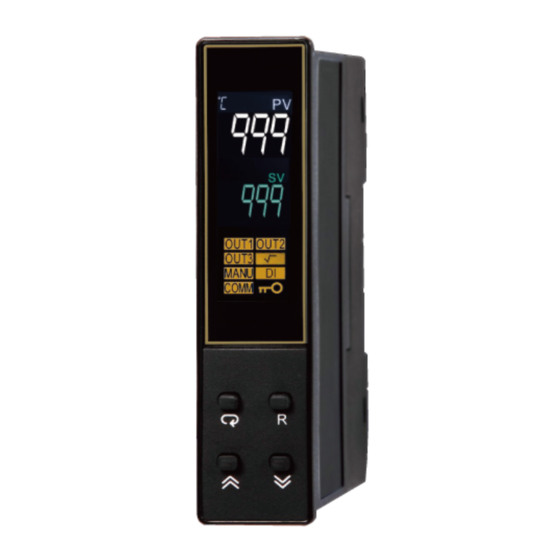
1. Introduction 1.1 Introduction DST01 The signal conditioner incorporates two bright and easy to read LCD displays which indicate process value(PV) and user selected parameter. Powered by a DC 12 ... 38 V or AC 95 ... 250 V supply. It is fully programmable for linear voltage, linear current, Pt100 and thermocouple types such as J, K, T, E, B, R, S, N, L, U, P, C, and D input. -
Page 5: Programming Port
DST01 Signal / Meter DST01 Universal Isolation Signal Converter / Splitter 1.3 Programming Port A Micro USB programming port is available for automatic configuration, calibration and firmware upgrades without the need to access the keys on the front panel. Front Panel... -
Page 6: Display Board Keys
DST01 Signal / Meter DST01 Universal Isolation Signal Converter / Splitter 1.4 Display Board Keys There are 4 Keys available in the display board for the user to operate as explained below. SCROLL KEY or ENTER KEY: This key is used to select a parameter to be viewed or adjusted. - Page 7 DST01 Signal / Meter DST01 Universal Isolation Signal Converter / Splitter Front Panel How Character are Displayed on the LCD screen www.eyc-tech.com ‧ ‧ ‧...
-
Page 8: Menu Flowchart
DST01 Signal / Meter DST01 Universal Isolation Signal Converter / Splitter 1.5 Menu Flowchart The Menu has been divided into 5 groups. They are as follows: Basic Menu Output Menu(oUt) Communication Menu(CoMM) Manual Mode Menu(MANU) Calibration Menu(CALI) - Page 9 DST01 Signal / Meter DST01 Universal Isolation Signal Converter / Splitter (2) Output Menu (oUt) key to get oUT in the lower display then use key to enter to output menu parameters. O1TY ANL1 ANH1 PV,MV PASS=CODE otZ1 otS1 O2TY...
- Page 10 DST01 Signal / Meter DST01 Universal Isolation Signal Converter / Splitter (3) Communication Menu (CoMM) key to get CoMM in the lower display then use key to enter into communication menu parameters. AddR bAUd dAtA PASS=CODE PARI PV,MV StoP bASE...
- Page 11 DST01 Signal / Meter DST01 Universal Isolation Signal Converter / Splitter (4) Manual Mode Menu key to get MANU in the lower display then use key to enter into Manual Mode parameters. PV,MV PASS=CODE bASE CALI MANU CoMM PASS=CODE FILE www.eyc-tech.com...
-
Page 12: Parameter Availability Table
DST01 Signal / Meter DST01 Universal Isolation Signal Converter / Splitter (5) Calibration Mode key to get CALI in the lower display then use key to enter into Calibration Mode parameters. PASS=CODE KPAS=3418 Ad.Lo PV,MV Ad.HI Rtd.L Rtd.H bASE CJ.Lo CJ.HI... - Page 13 DST01 Signal / Meter DST01 Universal Isolation Signal Converter / Splitter Register Parameter Existence Conditions Address Notation Exists unconditionally DISP Exists unconditionally LCUT Exists unconditionally Exists if INPT selects 4 ... 20, 0 ... 20, 0 ... 50, 0 ... 60, SQRT 0 ...
- Page 14 DST01 Signal / Meter DST01 Universal Isolation Signal Converter / Splitter Register Parameter Existence Conditions Address Notation CJCL Exists unconditionally Exists unconditionally Exists unconditionally Exists if MV selects ON EROR Exists unconditionally MODE Exists unconditionally PROG Exists unconditionally CMND Exists unconditionally...
-
Page 15: Installation And Wiring
DST01 Signal / Meter DST01 Universal Isolation Signal Converter / Splitter 2. Installation and Wiring Sometimes dangerous voltages capable of causing death are present in this instrument. Before doing the installation or any troubleshooting procedures, the power to the equipment must be switched off and isolated. -
Page 16: Dimension
DST01 Signal / Meter DST01 Universal Isolation Signal Converter / Splitter 2.2 Dimension www.eyc-tech.com ‧ ‧ ‧... -
Page 17: Wiring
DST01 Signal / Meter DST01 Universal Isolation Signal Converter / Splitter 2.3 Wiring Sometimes dangerous voltages capable of causing death are present in this instrument. Before doing the installation or any troubleshooting procedures, the power to the equipment must be switched off and isolated. Units suspected of being faulty must be disconnected and removed to a properly equipped workshop for testing and repair. - Page 18 DST01 Signal / Meter DST01 Universal Isolation Signal Converter / Splitter (2). Power Wiring The device is designed to operate at either DC 12 ... 38 V or AC 95 ... 250 V depending on power input option ordered. Check that the installation voltage corresponds with the power rating indicated on the product label before connecting power to the controller.
- Page 19 DST01 Signal / Meter DST01 Universal Isolation Signal Converter / Splitter (5). Retransmission Output Wiring Output 1 4 ... 20 mA Output 1 Linear Current 0 ... 10 V Output 1 Linear Voltage Output 2 4 ... 20 mA Output 2 Linear Current 0 ...
- Page 20 DST01 Signal / Meter DST01 Universal Isolation Signal Converter / Splitter Output 3 4 ... 20 mA Output 3 Linear Current 0 ... 10 V Output 3 Linear Voltage (6). Digital Input Wiring The digital input can accept a switch (dry contact) or an open collector signal.
- Page 21 DST01 Signal / Meter DST01 Universal Isolation Signal Converter / Splitter (7). RS-485 Data Communication www.eyc-tech.com ‧ ‧ ‧...
-
Page 22: Programming
DST01 Signal / Meter DST01 Universal Isolation Signal Converter / Splitter 3. Programming During Power on the device will show the PV on the upper display and MV on the lower display. Press to enter the setup menu. Use keys to select the desired parameter. Use key to reset and go back to the home screen. -
Page 23: Output Type
DST01 Signal / Meter DST01 Universal Isolation Signal Converter / Splitter Conversion Curve for Linear Type Process Signal Formula:PV=INLO + (INHI•INLO)((S – SL) / (SH-SL)) Example:A 4 ... 20 mA current loop pressure transducer with a range of 0 ... 15 kg/cm is connected to the input. -
Page 24: User Calibration
DST01 Signal / Meter DST01 Universal Isolation Signal Converter / Splitter 3.8 User Calibration Each unit is calibrated in the factory before shipment. The user can still modify the calibration in the field. The basic calibration of the device is highly stable and set for life. User calibration allows the user to offset the permanent factory calibration in order to:... -
Page 25: Digital Filter
DST01 Signal / Meter DST01 Universal Isolation Signal Converter / Splitter 3.9 Digital Filter In certain applications, the process value is too unstable to be read. To improve this, a programmable low pass filter incorporated in the controller can be used. This is a first order filter with a time constant specified by the FILT parameter. -
Page 26: Digital Input
DST01 Signal / Meter DST01 Universal Isolation Signal Converter / Splitter RS-485 Setup (1). Set oFS1 to RS-485 (2). Set individual addresses for units connected to the same port. (3). Set the Baud Rate(BAUD), Data Bit(DATA), Parity Bit(PARI) and Stop Bit(STOP) such that these values are accordant with PC setup conditions. -
Page 27: Calibration
DST01 Signal / Meter DST01 Universal Isolation Signal Converter / Splitter 4. Calibration Do not proceed through this section unless there is a definite need to recalibrate the controller. All previous calibration data will be lost. Do not attempt recalibration unless you have appropriate calibration equipment. - Page 28 DST01 Signal / Meter DST01 Universal Isolation Signal Converter / Splitter Calibrate RTD Input Press key to get Rtd. L Parameter. Send a 100 Ω signal to the RTD input terminals according to the connection. Press l key for at least 5 seconds. The display will blink a moment, otherwise, the calibration failed.
- Page 29 DST01 Signal / Meter DST01 Universal Isolation Signal Converter / Splitter Calibrate Linear Input Press key and the display will show V1.L Send a 0 V signal to the V+ and V- terminals. Press key for at least 5 seconds. The display will blink a moment and a new value is obtained.
-
Page 30: Communication
DST01 Signal / Meter DST01 Universal Isolation Signal Converter / Splitter 5. Communication This chapter explains the Modbus Communication protocol of the signal conditioner using RS-485 communication. This supports only RTU mode. Data is transmitted as 8-bit binary bytes with 1 start bit,1 stop bit and optional parity checking(None, Odd, Even). Baud rate may be set to 2400, 4800, 9600, 14400, 19200, 28800, 38400, 57600 and 115200 BPS. -
Page 31: Exception Responses
DST01 Signal / Meter DST01 Universal Isolation Signal Converter / Splitter (3) Function Code 16: Preset Multiple Register Query(From Master) Response(From Slave) Slave address(1-247) Function code(16) The starting address of register Hi(0) The starting address of register Lo(0-79) The starting address of register Lo(128-131) No. -
Page 32: Error Code
DST01 Signal / Meter DST01 Universal Isolation Signal Converter / Splitter 5.3 Error Code The description of the Error code is explained below Error Display Description & Reason Corrective Action Code Symbol Communication error: Correct the communication software ER10 to meet the protocol requirements. -
Page 33: Scaling
DST01 Signal / Meter DST01 Universal Isolation Signal Converter / Splitter 5.6 Scaling The scale high / low values are defined in the following table for INLO, INHI, PV, ANL1, ANL2, ANL3, ANH1, ANH2 and ANH3 Condition Scale Low Scale High Non-Linear Input -1999.9... - Page 34 DST01 Signal / Meter DST01 Universal Isolation Signal Converter / Splitter (4). Enter Manual Control Mode Query H’48 H’68 H’27 Slave Address Function Code Register Address Data Hi / Lo CRC16 (5). Read All Parameters Query H’3E Slave Address Function Code...
- Page 35 Tel.: 886-2-8221-2958 Web : www.eyc-tech.com e-mail : info@eyc-tech.com www.eyc-tech.com ‧ ‧ ‧...
Need help?
Do you have a question about the DST01 and is the answer not in the manual?
Questions and answers