Subscribe to Our Youtube Channel
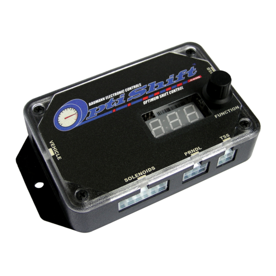
Summary of Contents for Baumann OptiShift
- Page 1 Transmission Control System Installation and Operation Manual for 4L60/4L80 transmissions...
- Page 2 Baumann Electronic Controls, LLC or Karl Baumann. The technology and processes contained in this product are proprietary and may be used only on a single unit basis or as defined by the written permission of Baumann Electronic Controls, LLC.
-
Page 3: Table Of Contents
CONTENTS Preparation Page 4 Connecting the OptiShift Page 5 Notes on Installation Page 7 Transmission Diagrams Page 9 Optional Accessories Page 11 Manual Shift Connections Overview Page 12 Manutronic Jumper Page 12 Push-buttons + On/Off Toggle Page 13 Push-buttons + On/Off Push-button... -
Page 4: Preparation
1993+ internal wiring harness. The Bosch pressure control solenoid used in pre-1994 4L80E transmissions is not compatible with the OptiShift TCS. You will need to upgrade it to the 1994+ Holley solenoid. The older Bosch solenoid is silver, while the newer Holley solenoid is black. -
Page 5: Connecting The Optishift
CONNECTING THE OPTISHIFT Step 1: Power Connect the power wire (red with 7.5A fuse) to the 12V switched power source of the Engine Control Unit (ECU). If your vehicle doesn't have an ECU, connect to another 12V ignition-switched power source. -
Page 7: Notes On Installation
Adaptation for Factory-Equipped Transmissions: It is possible to use the OptiShift TCS in a vehicle which was originally equipped with one of the intended transmissions. This could be done in conjunction with an engine management system upgrade that no longer supports the transmission. - Page 8 Identifying the Terminals of an Unknown Throttle Position Sensor: This is a procedure for identifying the correct terminal connections of any potentiometer-style throttle position sensor (almost all three-terminal TP sensors). A DVOM or analog Ohmmeter is required. 1. Set the meter to resistance mode and set it to a scale that can read up to 10K or 20K Ohms (if it is not auto-ranging).
-
Page 9: Transmission Diagrams
TRANSMISSION DIAGRAMS... -
Page 11: Optional Accessories
OPTIONAL ACCESSORIES Table Select: The table selection switch should be an On-Off type switch (such as a toggle or latching push-button switch) which applies ground to the table select input at Vehicle connector pin 5 when turned on. When the switch is turned on, the TCS will use the secondary calibration tables, allowing a completely different calibration to be selected for the transmission at any time. -
Page 12: Manual Shift Connections
Depending on your Manutronic configuration, you may need to install or uninstall the Manutronic jumper (JW2-5). You can find the jumper settings manual on the OptiShift software disc in PDF format. This jumper supplies 5V to the Manutronic 1 input and should be installed for all Manutronic configurations (except for a Ford cruise control system). -
Page 13: Push-Buttons + On/Off Toggle
680 Ohm resistor between them. (Follow the guidelines for soldering found in the “General Installation” section.) Remember that the Manutronic jumper must be installed in the OptiShift TCS and the correct settings used in the Shiftware setup. Manutronic will be enabled when the toggle switch is turned... -
Page 14: Push-Buttons + On/Off Push-Button
Light Blue up-shift wire. (Follow the guidelines for soldering found in the “General Installation” section.) Remember that the Manutronic jumper must be installed in the OptiShift TCS and the correct settings used in the Shiftware setup. To enable the Manutronic, press... -
Page 15: Tm Receiver
/ off switch or a toggle on / off switch. Refer to the previous two sections on how to install and use the on / off switch. Remember that the Manutronic jumper must be installed in the OptiShift TCS and the correct settings used in the Shiftware setup. -
Page 16: Shiftware
OptiShift unit in real-time. Setup: To create a calibration for the OptiShift, you can either use the wizard or load one of the supplied files included on the Shiftware disc. To use the setup wizard, click the New button. -
Page 17: Customize
Customize: The main window is where all of the shift points and line pressure editing is done. The graph displays the up-shift and down-shift speeds in relation to throttle position for each shift. It also displays the line pressure curve (otherwise known as the EPC current) in relation to throttle position. -
Page 18: Tables
Open. Writing a Calibration to the OptiShift: For the changes you've made to take effect on the OptiShift TCS, you first must write the calibration to the unit. Connect the OptiShift to your computer using a standard USB cord (Type A to Type B). -
Page 19: Important Information
IMPORTANT INFORMATION How to Avoid Errors: The Shiftware software gives you complete freedom and flexibility to customize your shifting calibration however you want. This freedom requires diligence to avoid errors. It is very important that the up-shift and down-shift curves for a given gear do not cross. -
Page 20: Troubleshooting
If the transmission does not begin to operate correctly within the first few feet of the road test, STOP immediately, check the troubleshooting guide, and call Baumann Electronic Controls if you need assistance. In some cases, just a few blocks of operation with low fluid pressure can destroy a transmission.


Need help?
Do you have a question about the OptiShift and is the answer not in the manual?
Questions and answers