
Summary of Contents for Equustek DLPCIe Series
- Page 1 DLPCIe User’s Guide Revision 1.03 – Feb. 20th, 2017 Equustek Solutions, Inc. Suite 286, 5489 Byrne Rd. Burnaby, BC, Canada V5J 3J1 Toll Free: 888-387-3787 http://www.equustek.com...
-
Page 2: Table Of Contents
Table of Contents 1.0 DLPCIe General Operation & Applications ..................3 2.0 Hardware Specifications ........................3 2.1 Operating Specifications: ..........................3 2.2 Physical Specifications: ..........................3 3.0 DLPCIe-Hardware Layout ........................4 4.0 Mode of Operation ..........................4 4.1 Online Mode of Operation ..........................4 4.2 Offline Mode ..............................4 4.3 BIOS Manager Options ..........................5 5.0 Switch and LED Indicator Functions ......................6... -
Page 3: Dlpcie General Operation & Applications
Website. Currently there are two standard DLPCIe products available to allow access to A-B’s DH-485 and DH+ network. Contact Equustek Solutions to see if the DLPCIe is the correct device for your communication needs. The DLPCIe-DF1 is a two port device that allows your DF1 driver to communicate with ones on an Allen Bradley DH-485 or DH+ network. -
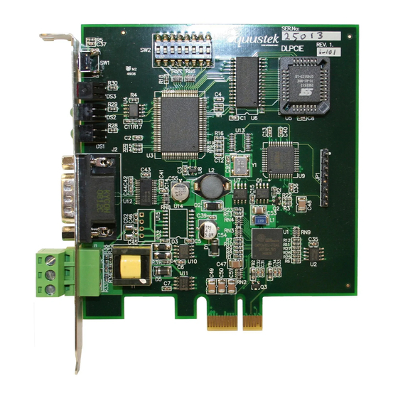
Page 4: Dlpcie-Hardware Layout
3.0 DLPCIe-Hardware Layout This Section contains information of the physical position and purpose of the components of the DLPCIe. At the top of the bracket has Configure pushbutton CHA DH+ or DH-485 3 pin Screw terminal (Phoenix Type) pin 1 is the bottom one. ... -
Page 5: Bios Manager Options
.txt file to send, or send the Text File under HyperTerminal. Wait for an “*A-OK* BURN COMPLETE!” message to appear. 3. Memory Dump This is used to display the RAM memory of the DLPCIe. This should only be done after contacting Equustek Solu- tions to debug problems. 4. Off-Line Diagnostics Starts a series of tests to test the DLPCIe’s hardware and should only be done if instructed so by a trained person. -
Page 6: Switch And Led Indicator Functions
5.0 Switch and LED Indicator Functions 5.1 Switch Functions The Configure pushbutton takes the DLPCIe out of On-Line operation mode and puts it in the BIOS Manager mode. The BIOS Manager mode also allows for configuration parameters to be downloaded from or uploaded to the Windows based configuration software (EQ32). When this mode has been entered the STATUS LED will be RED and BUS LED will be Green while NET LED will be off. -
Page 7: Off-Line Modes
keeps repeating. Settings (See Section 1.1) and then reconfigure the unit. 5.2.4 Off-Line Modes The following table describes the meaning of LED patterns in the different Off-Line modes of operation. LED Pattern Description of Operation STATUSLED ON BIOS Manager/Configuration Parameter Download/Upload NETLED OFF and BUSLED ON All Three LED’s ON Offline Debug Mode... -
Page 8: Dlpcie Wiring Diagrams
6.0 DLPCIe Wiring Diagrams 6.1 Online Cable DLPCIe-CHA DH+ DLPCIe-CHA DH+ Other DH+ Nodes Note: Clear & Blue might have to be swapped depending on existing DH+ wiring 6.2 Online Cable DLPCIe-CHA DH-485 DLPCIe-CHA DH-485 Other DH-485 Nodes 7.0 DLPCIe DH-485/DH+ Networking Applications 7.1 DLPCIe-DF1 –... -
Page 9: Appendix A: Installing The Rs232 Serial Driver For The Pci Express Bus
Appendix A: Installing the RS232 Serial Driver For the PCI Express BUS A1- Screen shots for an example of installing a driver for Windows XP are shown below... - Page 10 After installing the driver please make sure that it is installed correctly by checking it under the device manager, it should be some thing like it is shown below but with different port number depending on what is installed in the PC. The COM Port with lowest number is the one to be used for the DF1 Driver.
- Page 11 A2- Equustek DLPCIe ( Allen BradleyDF1 to DH+ / DH485 ) PCI Express Bus Card with Windows 7 In case Windows 7 does not successfully install the DLPCIe driver like what you see in the following screen shots. Click on Change setting..
- Page 12 Change it to Automatic update.
- Page 13 And if it still does not find the driver like what you see below. Then go to your device manager and look under ports and LPTs and click on update driver software.
- Page 14 Choose Browse my computer. Browse to where the SW_Windows_PCIe_NativeUart folder is on your CD and click on Next...
- Page 15 Wait until you see...
- Page 16 The two serial port numbers will differ from one PC to another and you can change the number to your desired available one. That will complete the installation of the PCI Express driver for the card. please note that in Win7 the second port is used for setting up the DF1 drive, later on.
-
Page 17: Appendix B: Configuring The Dl_Pci Express Bus Card
Appendix B: Configuring the DL_PCI Express BUS card 1- Using the EQ32 configuration software to configure the unit, all the screen shots below show an example of that. Click on the DLPCIe Button Select the DF1 Com port that was found under the Device Manager, then click on the Offline Manager button, you should see some thing like the screen below. - Page 18 This confirms that the serial port is working, click on close. Then click on Configure button. It should come up with the screen shot shown below. Click on Next On next screen shot select the Network mode DH+ or HD485 and also select the node address number in Octal, please make sure that it is not a duplicate.
- Page 19 Here select the Network Speed . Click on Next then enter the DF1 serial Parameters shown below.
- Page 20 Click on Next and make sure that the unit is in configure mode other wise press the configure button as shown below. Click on Ok then on Next. It should come with what is shown below Click on Ok, then on Finish, and close the EQ32 program.
-
Page 21: Select The Network Node Address And Baud Rate Settings
2- Configuring the Card using the Switch SW2: 2.1Select The Network Node address and Baud rate settings: Please not that SW ON= 0 and SW OFF =1 Network Switches 2-1 Baud Rate 230.4Kbaud OFF-OFF 115.2Kbaud OFF-ON 57.6Kbaud ON-OFF EEPROM ON-ON Node Address Switches 8-7-6-5-4-3 Octal... - Page 22 As for the DF1 parameters they are preconfigured as shown below. If different settings are required please use the EQ32 to configure the unit with the EEPROM as shown in the previous step.
Need help?
Do you have a question about the DLPCIe Series and is the answer not in the manual?
Questions and answers