Table of Contents
Advertisement
Quick Links
Advertisement
Table of Contents

Summary of Contents for LEYRO LDT 2000
- Page 1 LDT 2000 PRECISION THERMOMETER MANUAL...
- Page 2 Leyro Instruments® doesn’t accept warranty and liability claims neither upon this publication nor in case of improper treatment of the described products. The document may contain technical inaccuracies and typographical errors. The content will be revised on a regular basis. These changes will be implemented in later versions.
-
Page 3: Table Of Contents
4.2 Probes 4.3 Extender 4.4 Resistance calibration 4.5 Coefficients 4.6 PC interface 5. TyPICAL PERFORmANCE OF ThE LDT 2000 ThERmOmETER 6. ThERmOmETER UTILITy SOFTwARE 6.1 Program at a glance 6.1.1 Installation and requirements 6.1.2 Main window overview 6.2 Viewing and setting up the chart 6.3 Recording measured data... - Page 4 7. COmmUNICATION PROTOCOL 7.1 Communication interfaces 7.2 SCPI protocol 7.2.1 Syntax 7.2.2 Commands 7.2.3 Command termination character 7.2.4 Structure of commands 7.2.5 Query 7.2.6 Parameters 7.2.7 Special commands 7.2.8 Special characters 7.2.9 Commands’ execution 7.2.10 Default commands 7.3 Status registers 7.3.1 STB status register 7.3.2 Events register (ESR) 7.3.3 Operation register (OPER)
- Page 5 7.6.2.3 :CONFigure? 7.6.2.4 Result readout commands :FETCh? and :READ? 7.6.2.5 :MEASure? 7.6.3 :UNIT – measurement’s units handling 7.6.4 :INPut – measurement circuit configuration 7.6.4.1 :FILTer – configuration of line frequency filter 7.6.5 :SENSe – configuration of measurement’s parameters 7.6.5.1 :AVERage – measurement averaging 7.6.5.2 :OVERflow –probe’s temperature range exceeding flag 7.6.6 :CALibration – calibration commands 7.6.6.1 :ALL – autocalibration 7.6.6.2 :SECure – calibration unlocking 7.6.6.3 :RESistance –...
-
Page 6: General
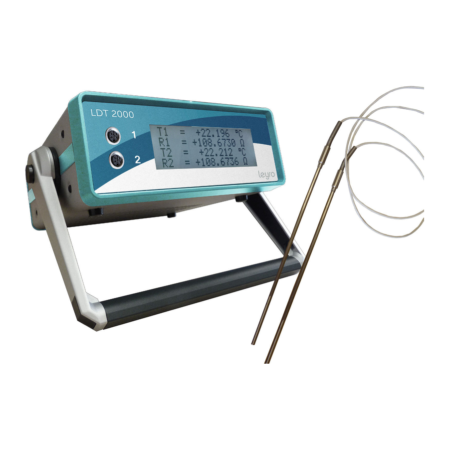
The mains socket should always have working grounding path! 2. PRODUCT DESCRIPTION The LDT 2000 is a laboratory- grade precision digital thermometer which uses Pt-100 pla- tinum resistors as temperature sensors. The device provides two measuring channels. The range of measured temperatures is from -150°C to +350°C for option 0x, and from -150°C to +850°C for option 1x (measuring circuit limitation, probe may have its own limitations). -
Page 7: Features
Current Reversal technique. The autocalibration sequence is a background task performed continuously. The LDT 2000 has been designed to make operating as simple as possible. An advanced configuration and data acquisition options are available by the means of PC interface and suitable PC software. A large illuminated LCD display is capable of indicating several parameters simultanously. -
Page 8: Operation
3. OPERATION 3.1 Safety The LDT 2000 temperature meter is a device designed for laboratory, indoor use. It is powered from 85 to 250V line, therefore the user should work with respect to all precau- tions related to operating with mains powered equipment. The mains socket should always have working grounding path! 3.2 Preparation to work... -
Page 9: Power-On Sequence
Following steps are required only if operation with Thermometer Utility software is required 7. Please install USB driver and Thermometer Utility software prior to the first thermometer connection 8. Connect the thermometer to the PC computer using USB or RS-232 cable 9. Run Thermometer Utility software 10. -
Page 10: Stand- Alone Benchtop Operation (Without Pc)
1 is beeing measured at the moment. 3.4 Stand- alone benchtop operation (without PC) The LDT 2000 has been designed to make operating as simple as possible. Follow steps from chapter 3.2. 3.5 Operation with PC and Thermometer Utility software The Thermometer Utility software was developed for easy intuitive data acquisition from the LDT 2000 thermometer. The software is available for Microsoft Windows Operating... -
Page 11: Internal Battery
Lithium battery 3V type CR 2032. 3.8 Calibration period The manufacturer suggest 24 months calibration interval for the LDT 2000 device. The probes should be calibrated: – every 24 months if the working temperature is T < 200 °C – every 12 months if the working temperature is T ≥ 200 °C... -
Page 12: Extender
Using long extender in industrial environment with very high electromag- netic interferences level can increase the measurement noise. 4.4 Resistance calibration In case of performing resistance calibration procedure or using the LDT 2000 as a pre- cision ohmmeter the user should follow connection scheme shown on fig 6 and use the Amphenol C091-T3400-001 connector for connecting external measured resistor. It is ne- cessary to short two middle pins of the connector to provide the „probe detect loop”. If the... -
Page 13: Coefficients
The most frequently used commands are listed below (this symbol // marks the comment): *idn?$00 //identify command, response will be eg. „Leyro Instruments, LDT 2000 OPT02, 0413,1.1” :syst:date?; time?$00 //date and hour question :syst:date 2013,04,04;... - Page 14 5. TyPICAL PERFORmANCE OF ThE ThERmOmETER...
-
Page 18: Thermometer Utility Software
6. ThERmOmETER UTILITy SOFTwARE 6.1 Program at a glance Thermometer Utility software allows to use LDT 2000 thermometer with PC computer. It allows to use all benefits of data acquisition and remote configuration of the thermometer. The software can be easily installed on any MS Windows Operating System and requires RS232 (COM) or USB port to connect. 6.1.1 Installation and requirements To start the installation, run “setup.exe” file and confirm to deploy the program. After quick setup, utility runs for the first time. Later it will be available from desktop shortcut (fig 13). fig 13: Thermometer Utility icon Thermometer Utility was developed on .NET Framework and requires at least 2.0 version of this platform to work. -
Page 19: Main Window Overview
6.1.2 Main window overview Thermometer Utility main window consists of few parts, shown and marked on fig 14. Tool bar on top, allows to select and to connect with chosen thermometer. During startup, the program searches for compatible devices on available serial communication ports. Afterwards, the amount of devices found is displayed on status bar (bottom part of the win- dow). -
Page 20: Viewing And Setting Up The Chart
6.2 viewing and setting up the chart Chart component can display function curves of two of possible values at a time: • TEMP1 or TEMP2 – temperature values; • GRAD1 or GRAD2 – gradients; • RES1 or RES2 – resistance values. • DIFF -difference in temperatures T1-T2 As it is shown on fig 15, secondary function can be turned off, by choosing “None” from selection list. Subsequent measured values are being appended at the end of chart, therefore since the start of collection, it “grows” to the right. The chart can store up to 24 hours of samples, and after that time, the chart stops receiving further data. -
Page 21: Recording Measured Data
Below selection combo, there are three fields that determine the scale for each function: • max – as for maximum value of vertical scale, • min – as for minimum value of vertical scale, • div – as for amount of divisions of vertical scale range. Changing each field takes an immediate effect on chart component. In case of invalid input, a small exclamation icon will appear, showing fault information after holding the mouse cursor over it. Timeline settings are reduced to specification of time span (maximum of 86400 seconds = 24 hours), and division of time-scale. Besides possibility of changing the width of time win- dow, there is also a chance to scroll its starting position, by modifying the time offset field. Chart parameters, that have up/down arrows attached, can be edited using two basic ways: mouse-click of an arrow or entering new value from keyboard and confirming with Enter key. But there are also two convenient ways – after selecting such field with mouse, it can be scrolled up/down using respective keyboard up/down keys, or with mouse wheel... -
Page 22: Storing And Using Recorded Data
As it is shown on the figure, user can select which levels should be recorded, by marking (or deselecting) fields indicating channels (CH1, CH2) and values (TEMP, GRAD, RES). In case when one of probes is not used (not connected), corresponding fields are disabled (grayed). To have a quick start, user can press START button right away, to view subsequent levels being appended on the right, each one second (by default). Current recording can be stopped, using STOP button. There are however few more options, which allow scheduling samples collection. First, it is possible to enlarge the time interval between consecutive samples (in seconds, one is a minimum). -
Page 23: Configuration
OpenOffice Calc from context menu). 4. In “Text import” dialog window of Calc, select “Unicode (UTF-8)” as used character set and mark “Comma” as the field separator only. Press OK to continue. 5. Format data cells corresponding to their type (numbers as Number type, date-time fields using suitable date-time format). 6.4 Configuration Simple thermometer configuration is available under CONFIG button, located in the top toolbar of the program. After pressing this button however, samples capturing is held until leaving configuration window. The above fig 19 shows options, explained in subsequent paragraphs: • Display – here user can switch between several functions, deciding which of these should be presented on thermometer’s LCD display below temperature reading. The functions are described below: GRADient – the temperature gradient per second DIFFerence –... -
Page 24: Calibration
6.5 Calibration More advanced features are provided in Calibration window, accessible through its corres- ponding button on the top toolbar. After entering, user can see a similar window to this in fig 20. In case if only one probe is attached to the thermometer, program will display a message and present only the parameters of connected probe. -
Page 25: Usb Drivers
• TMAX - maximum working temperature for probe, • Tmin overflow , Tmax overflow - the fields are used to confirm that the probe mantains it is metrological properties and allow to check if the probes was used within declared temperature range. If any time during lifespan the particular temperatu re limit has been exceeded, the thermometer sends back OVF condition is set if within the following 20 measurements of temperature, over 10 measurements exceeds the limit. -
Page 26: Communication Protocol
7. COmmUNICATION PROTOCOL for firmware versions 1.23 … 1.24 7.1 Communication interfaces Communication with the thermometer can be implemented using RS232 (baud rate = 9600, data bits = 8, parity = none, stop bits = one, handshaking = none) or USB 2.0 interfa- ce. USB protocol works as a virtual COM port, and uses the STM Virtual COM Port drivers. 7.2 SCPI protocol An IEEE-488.2-based protocol is used to communicate with the thermometer, implemen- ting SCPI commands. -
Page 27: Query
to access the value of temperatue, following command must be sent: :MEAS:TEMP:VAL? While decoding a sequence of commands, the thermometer stores the catalogue, where it currently points. Therefore in case of the example above, if desiring to access the tempera- ture gradient also, it can be achieved in two ways: 1) :MEAS:TEMP:VAL?; GRAD? 2) :MEAS:TEMP:VAL?; MEAS:TEMP:GRAD? After running :MEAS:TEMP:VAL? command, we’re residing already in TEMP catalogue, therefore we can directly use another command from that catalogue (example 1). -
Page 28: Commands' Execution
7.2.9 Commands’ execution There are two possible methods of executing commands in the standard: holding and non- holding. In case of the first one, a command is executed until the previous one finishes. In case of non-holding option, commands are performed in parallel. Thermometer runs commands in holding mode, which means in some cases it is required to wait over a dozen of seconds before achieving a response from device. -
Page 29: Events Register (Esr)
• 3 bit QUES – logical sum of reliability register (QUES); • 4 bit MAV (Message Available) – value equal to 1 if transmission buffer contains messa ges; it is always 0 in thermometer, since it responds instantly; • 5 bit ESB – logical sum of events register (ESR); • 6 bit RQS – logical sum of STB status register; • 7 bit OPER – logical sum of operation register (OPER). 7.3.2 Events register (ESR) Eigth-bit register, which stores some of the events occurring in the device. When an event happens, bits are set, but not reset after it passes. Reading contents of the register resets it however. Register’s bits have following meaning: • 0 bit OPC – if the bit is set, it means all tasks were accomplished; is set only after calling *OPC command;... -
Page 30: Mask Registers
(the second option means a range of channels). Thermometer implements both options: • (@1,2) or (@1:2) – double-channel measurement. The standard also defines, that the device should interpret channels order properly. So (@2,1) should cause the second channel to be received on first position. Thermometer recognizes channels’ numbers correctly, but will always respond in 1,2 order. Such incon- sistency with SCPI standard will likely be fixed in future releases of the device. 7.5 Special commands LDT 2000 thermometer implements all special commands required by the standard: • *CLS – resets all status registers: STB, ESR, OPER, QUES, as well as errors query; it does not however influence registers’ masks; • *ESE<int> - sets the mask of events register (ESR) to decimal value passed as parame- ter;... -
Page 31: Thermometer Commands Catalogue
• *ESE? - reads the value of events register mask (ESR); • *ESR? - reads the value of events register (ESR); afterwards, the register is reset; • *IDN? - device identification; thermometer sends back an answer containing four fields separated with commas: manufacturer’s name, device model, serial number and firmware version; • *OPC – termination of current operation, sets OPC bit in ESR register; • *OPC? - queries the termination of current operation, sends 1 after finishing all com- mands before receiving the query; • *RST – device reset; thermometer is set to state as it was after switching the power on. It is single channel measurement from first probe (or second, if the first is not present). Era- sure of sent results and thermometer’s triggers. Turns of result averaging. The command doesn’t change values of status registers, registers’ masks, nor errors query. • *SRE<int> - sets the mask of status register (STB) to decimal value passed as parame- ter; • *SRE? - reads the value of status register mask (STB);... - Page 32 :[VALue]? <channel list> :GRADient? <channel list> :DIFFerence? <channel list> :RESistance? <channel list> :UNIT :TEMPerature <unit> :INPut :FILTer :NOTCh <f value> [:SENSe] :AVERage :COUNt <cycles> :OVERflow :CH1 (CHannel1) :TMIN? :TMAX? :CH2 (CHannel2) :TMIN? :TMAX? :CALibration [:ALL] [:ALL]? :SECure [:STATe] <boolean, [password]> :RESistance :VALue <R value> :VALue? <R value>...
-
Page 33: Measurement Commands
:MENU [:NAME] <name> :STATus :OPERation [:EVENt]? :ENABle <int> :QUEStionable [:EVENt]? :ENABle <int> :PRESet :SYSTem :ERRor [:NEXT]? :DATE <year, mounth, day> :TIME <hour, minute, second> 7.6.2 Measurement commands These commands are used to perform measurements. They’re groupped into following catalogues: :INITiate :CONFigure :FETCh? :READ? - Page 34 To measure temperature on second channel: 1) :CONF:TEMP:VAL (@2) 2) :CONF:TEMP (@2) 3) :CONF (@2) Measurement of gradient or resistance, requires providing full path of commands. To mea- sure gradient on first channel, configure using one of following commands: 1) :CONF:TEMP:GRAD (@1) 2) :CONF:TEMP:GRAD. Measurement of Pt100 probe’s resistance for both channels can be setup using: :CONF:TEMP:RES (@1,2) Measurement of temperature difference between channels 2 and 1 can be setup using: :CONF:TEMP:DIFF (@2,1)
- Page 35 7.6.2.5 :MEASure? This command is used for configuration and execution of measurement, including returning of the result. It can be treated as equal to sending: 1) :CONFigure:... 2) :READ? commands. Method of measurement configuration is identical as in case of :CONFigure command. 7.6.3 :UNIT – measurement’s units handling The command is used for setting and checking the temperature units used for displaying and calculations.
- Page 36 helps in gaining more stabile result, for longer period of measurement. 1 to 10 cycles can be averaged, where 1 means that no averaging is done at all. :AVERage command contains one sub-command :COUNt, used for specifying the amount of averaged cycles. It was added to provide more compatibility with SCPI standard.
- Page 37 7.6.6.2 :SECure – calibration unlocking This command secures access to calibration functions, to prevent incidental overwriting of settings, by sending one of calibration commands. To unlock calibration procedures, securi- ty mode must be turned off, by sending ASCII string “2804” as parameter of the command: 1) :CAL:SEC:STAT ON, 2804 2) :CAL:SEC 1, 2804 After performing calibration, secure mode can be turned off: 1) :CAL:SEC:STAT OFF 2) :CAL:SEC 0 Password isn’t required to turn off, but may be used anyway.
- Page 38 7.6.7 :MEMory – internal EEPROM memory handling This directory is used to operate the EEPROM memories located on the analogue board and the EEPROMs inside the thermometer probes. In firmware version 1.24 the only active memory function is clearing memory :CLEar. It allows to delete data in the memory asso- ciated with the module. The thermometer has three defined memory areas: • METer – memory located on the analogue (measuring) board: resistance calibration data, board’s serial number. • CH1 (CHannel 1) – the memory associated with the probe in the channel 1 : memory in- side the probe , as well as an area dedicated to the memory of the probe on the analogue board.
- Page 39 7.6.9 :STATus – status registers handling Commands grouped in that catalogue, are used for handling additional status registers, which are OPER and QUES. Main status registers (STB and ESR) are handled through special commands. 7.6.9.1 :OPERation – operation register Handles the operation register (OPER). • :EVENt? - reads the contents of operation register, • ENABle <int> - sets the register mask of OPER status register.
- Page 40 • 104 CALIBRATION EXECUTE – can’t execute command, since calibration is running, • 110 CALIBRATION ERROR – resistance calibration error, notified in case when the devi- ce can’t specify error’s cause, • 111 CALIBRATION START ERROR – can’t start resistance calibration, • 112 RESISTOR MISSING – external standard resistor not connected, • 113 RESISTOR LOW – external standard resistor has too low resistance, • 114 RESISTOR HIGH – external standard resistor has too high resistance, • 120 PROBE CALIBRATION ERROR – probe calibration error, notified in case when it is not possible to give precise error description, • 121 R0 LOW– too low resistance of sensor for 0 °C temperature, • 122 R0 HIGH – too high resistance of sensor for 0 °C temperature, • 123 TEMPERATURE LOW– too small value of temperature, can be notified when ente- ring TMIN and TMAX, • 124 TEMPERATURE HIGH – too big value of temperature, can be notified when entering TMIN and TMAX, • 130 CALIBRATION SECURE ERROR – write protection for calibration data is on. • 140 MEMORY ERROR – both hardware error and triple write or read error, • 141 CHANNEL1 MEMORY ERROR – no communication with probe in CH1, • 141 CHANNEL2 MEMORY ERROR – no communication with probe in CH2, • 143 METER MEMORY ERROR – no communication with analogue board memory • 150 CALCULATION ERROR – error occurring when using certain coefficients the algori- thm is divergent or gives forbidden results, • 151 CALCULATION ERROR – calculation error for probe in CH1 • 152 CALCULATION ERROR – calculation error for probe in CH2 7.7.2 SCPI errors • 100 COMMAND ERROR – notified in case, when command error cannot be described more precisely,...
- Page 41 NOTES _______________________________________________________________________ _____________________________________________________________________________ _____________________________________________________________________________ _____________________________________________________________________________ _____________________________________________________________________________ _____________________________________________________________________________ _____________________________________________________________________________ _____________________________________________________________________________ _____________________________________________________________________________ _____________________________________________________________________________ _____________________________________________________________________________ _____________________________________________________________________________ _____________________________________________________________________________ _____________________________________________________________________________ _____________________________________________________________________________ _____________________________________________________________________________ _____________________________________________________________________________ _____________________________________________________________________________ _____________________________________________________________________________ _____________________________________________________________________________ _____________________________________________________________________________ _____________________________________________________________________________ _____________________________________________________________________________ _____________________________________________________________________________ _____________________________________________________________________________ _____________________________________________________________________________ _____________________________________________________________________________ _____________________________________________________________________________ _____________________________________________________________________________ _____________________________________________________________________________ _____________________________________________________________________________ _____________________________________________________________________________ _____________________________________________________________________________ _____________________________________________________________________________ _____________________________________________________________________________ _____________________________________________________________________________ _____________________________________________________________________________ _____________________________________________________________________________ _____________________________________________________________________________ _____________________________________________________________________________ _____________________________________________________________________________ _____________________________________________________________________________ _____________________________________________________________________________...
- Page 42 CENTRAL OFFICE: LEYRO INSTRUMENTS SL Avda. Somosierra 24 28703 San Sebastián de los Reyes Madrid Tel: +34 912 835 502 info@leyro.net www.leyroinstruments.com...
Need help?
Do you have a question about the LDT 2000 and is the answer not in the manual?
Questions and answers