Advertisement
Quick Links
CONFIDENTIAL
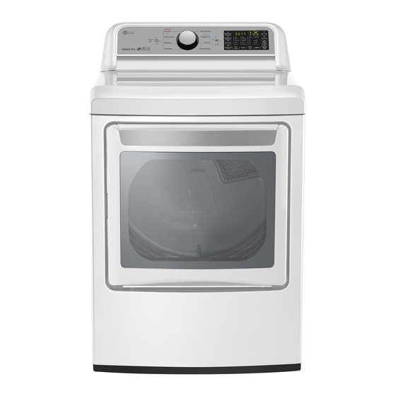
MODEL :
DLEX7200* DLGX7201*
Any reproduction, duplication, distribution (including by way of email, facsimile or other electronic means),
publication, modification, copying or transmission of this Service Manual is STRICTLY PROHIBITED
unless you have obtained the prior written consent of the LG Electronics entity from which you received this
Service Manual. The material covered by this prohibition includes, without limitation, any text, graphics or
logos in this Service Manual.
Copyright ©
2016 - 2017
LG Electronics Inc. All rights reserved. Only training and service purposes.
Advertisement


Need help?
Do you have a question about the DLEX7200 Series and is the answer not in the manual?
Questions and answers
instructions for removing the back cover on an LG DLE7200E Dryer
To remove the back cover on an LG DLE7200E dryer:
1. Remove one screw to take off the safety cover.
2. Remove the six remaining screws on the panel rear.
3. Lift out the back panel.
Be careful when handling screws and panels to avoid damage.
This answer is automatically generated