
Subscribe to Our Youtube Channel
Summary of Contents for Haulotte Group HTL 4010
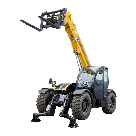
- Page 1 Operator's manual Operator's manual TELESCOPIC HANDLERS HTL 4010 - HTL 3510 - HTL 3210 2420344510 E 11.11 2420344510 E 11.11...
- Page 2 Telescopic handlers 2420344510 E 11.11...
-
Page 3: Table Of Contents
Operator's manual CONTENTS 1 - Operator's manual ....... 2 - After Sales Service ....... 3 - Compliance . - Page 4 Operator's manual OPERATION 1 - Engine ........1.1 - Starting the engine.
- Page 5 Operator's manual 5.6 - 3 t (6615 lb) 1 m(3 ft3 in) jib crane ......5.6.1 - Characteristics .
- Page 6 Operator's manual TECHNICAL CHARACTERISTICS 1 - Main characteristics ......2 - Overall dimensions......3 - Working area .
- Page 7 Operator's manual 10 - Every 50 h hours of operation ....11 - Every 100 h hours of operation ....11.1 - Tyres .
- Page 8 Operator's manual 19 - Electric circuit ....... . 19.1 - Wiring diagram-Main components ......20 - Hydraulic circuit .
-
Page 9: Operator's Manual
Telescopic handlers You have just purchased a HAULOTTE® product and we would like to thank you for your business. 1 - Operator's manual As stated on the delivery slip, this manual is one of the documents in the on-board document holder provided upon delivery of your HAULOTTE®... -
Page 10: Compliance
Telescopic handlers 3 - Compliance We would like to remind you that HAULOTTE® complies with the provisions of any applicable directives applicable to this type of machine. HAULOTTE advises you that NO modifications carried out without the written permission of HAULOTTE® will void the HAULOTTE warranty.. HAULOTTE®... -
Page 11: Haulotte Services® Contact Details
Telescopic handlers HAULOTTE Services® contact details HAULOTTE Services® contact details 2420344510 E 11.11... - Page 12 Telescopic handlers 2420344510 E 11.11...
-
Page 13: Safety Precautions
Telescopic handlers - Safety precautions Safety precautions 1 - Recommendations 1.1 - OPERATOR'S MANUAL This operators manual is specific to the HAULOTTE® products listed on the cover page of this manual.. The operator manual does not replace the basic training required for all worksite equipment operators. HAULOTTE®... -
Page 14: Label Colors
Telescopic handlers - Safety precautions 1.3 - LABEL COLORS The potential dangers and any specific regulations are indicated around the product by labels and identification plates. The labels must be kept in good condition. Additional labels can be obtained from HAULOTTE Services®. Familiarize yourself with the labels and their respective color codes. -
Page 15: Potential Risks
Telescopic handlers - Safety precautions 2.2 - POTENTIAL RISKS 2.2.1 - Tip-over hazards Never use an accessory without having checked the HAULOTTE® accessory load capacity chart installed on the telehandler. • Do not exceed the rated lifting capacity. • Check that the ground can support the machine. Do not drive at high speed with the boom raised. - Page 16 Telescopic handlers - Safety precautions Do not level the machine with the boom or the accessory above 30 ° • Transport the load as low as possible. Attach the suspended loads to restrict movement. • Comply with the capacity charts displayed in the cab. •...
-
Page 17: Electrical Hazards
Telescopic handlers - Safety precautions • Always wear the seat belt. Do not hang your head, your arms, your hands, your legs or any other parts of your body out of the cab. If the telehandler starts to tip over : •... -
Page 18: Travel Hazards
Telescopic handlers - Safety precautions Minimum safety distance Electric voltage Minimum safety distance Mètre Feet 0 - 300 V Avoid contact 300 V - 50 kV 50 - 200 kV 200 - 350 kV 350 - 500 kV 500 - 750 kV 750 - 1000 kV N.B.-:-This table is applicable, except when the local regulations are more strict. -
Page 19: Load Falling Hazards
Telescopic handlers - Safety precautions • Before moving the machine, ensure that the path is clear and sound the horn. • When driving, retract the boom and keep the boom and the attachment as low as possible. • Maintain visibility of the mirrors and optimal visibility of the path of travel. -
Page 20: Mechanical Attachment Locking Device
Telescopic handlers - Safety precautions 2.2.5 - Mechanical attachment locking device • Ensure that the machine is placed on a firm and level surface. • Actuate the parking brake. Blocking the wheels is also recommended. • Level the handler both sideways (chassis swaying) and lengthways (accessory tilt). •... -
Page 21: Pinching And Crushing Hazards
Telescopic handlers - Safety precautions 2.2.7 - Pinching and crushing hazards Stay clear of pinch points and rotating parts on the handler. Do not approach moving parts while the engine is running. Keep clear of the tires and the chassis or other steering parts when manoeuvring the telehandler. -
Page 22: Risk Of Falling
Telescopic handlers - Safety precautions 2.2.8 - Risk of falling Enter the cab using the proper hand rails and the steps provided. Always maintain 3 points of contact when entering or leaving the machine. Never grab the control levers or the steering wheel when mounting or dismounting the machine. -
Page 23: Intervenor's Responsibility
Telescopic handlers - Intervenor's responsibility Intervenor's responsibility 1 - Owner's (or hirer's) responsibility The owner (or hirer) has the obligation to inform operators of the instructions contained in the Operator Manual. The owner (or hirer) has the obligation to renew all manuals or labels that are either missing or in bad condition. -
Page 24: Inspection And Maintenance
Telescopic handlers - Intervenor's responsibility 5 - Inspection and maintenance The inspection and maintenance table below, identifies the role and the responsibilities of each party in periodical machine maintenance.. If the machine is operated in a hostile environment or intensively, increase the frequency of maintenance. Inspections and maintenance Type of Reference... -
Page 25: Pre-Operation And Controls
Telescopic handlers - Pre-operation and controls Pre-operation and controls 1 - Checks and inspection before use Each day and before the beginning of a new work period and on each change of operator, the machine must be subjected to a visual inspection and a complete functional test. Any repairs required must be performed before the machine is used, its correct operation depends on it. - Page 26 Telescopic handlers - Pre-operation and controls • Steering system's state : axles, wheels and tyres : • No cracks, distortions, damaged paint or other faults • No missing or loose bolts. • Condition of the tyres (cuts, excessive wear, etc.). •...
-
Page 27: Pre-Operation Checks And Inspection
Telescopic handlers - Pre-operation and controls 2 - Pre-operation checks and inspection N.B.-:-Perform all required maintenance work before operating the unit. Use extreme caution when checking parts that are difficult to reach. Use an approved ladder. "Failure" to comply with these instructions could result in death or serious injury. Increase in periodical inspections : •... - Page 28 Telescopic handlers - Pre-operation and controls Major Component Location Diagram Begin the walk-around inspection at item 1, as indicated below. Continue to the right (anticlockwise, when viewed from above) checking each part in sequence. N.B.-:-For each component, ensure that there are no loose or missing parts, that the components are securely fastened and that there are no visible leaks or excessive wear in addition to any other criteria mentioned.
- Page 29 Telescopic handlers - Pre-operation and controls Jib cylinders: lifting and telescopic action cylinders, compensation output, compensation input (crowding) and cases : • Pins secure, hydraulic hoses in good condition, no leaks. • Check the state of the extension booms wear pads. Left-hand stabiliser and detector : Pins secure, hydraulic hoses in good condition, no leaks (on HTL4010 and HTL3210 only).
- Page 30 Telescopic handlers - Pre-operation and controls Tilt correction cylinder : Pins secure, hydraulic hoses in good condition, no leaks (For HTL3510 only). Right-hand stabiliser and contactor : Pins secure, hydraulic hoses in good condition, no leaks (on HTL4010 and HTL3210 only). Attachment : Correctly installed( Section E - Attachments).
-
Page 31: Safety Stickers
Telescopic handlers - Pre-operation and controls 3 - Safety stickers Ensure that all stickers and appropriate capacity charts are legible and in place. Clean or replace if necessary. 3.1 - RED LABELS The red labels indicate a potentially fatal danger. Common labels - CE standard Specific labels HTL4010 - CE standard Specific labels HTL3210 - CE standard... -
Page 32: Yellow Labels
Telescopic handlers - Pre-operation and controls Specific labels HTL3510 - CE standard 3.2 - YELLOW LABELS The yellow labels indicate a risk of material damage and/or minor injury. Common labels Specific labels HTL4010 - HTL 3510 - HTL 3210 2420344510 E 11.11... -
Page 33: Other Labels
Telescopic handlers - Pre-operation and controls Specific labels, optional 3.3 - OTHER LABELS The other labels provide additional technical information. Common labels 2420344510 E 11.11... - Page 34 Telescopic handlers - Pre-operation and controls Specific labels HTL4010 Specific labels HTL3510 2420344510 E 11.11...
- Page 35 Telescopic handlers - Pre-operation and controls Specific labels HTL3210 Specific labels, optional 2420344510 E 11.11...
-
Page 36: Identification
Telescopic handlers - Pre-operation and controls 3.4 - IDENTIFICATION Localization: isometric view - HTL4010 - HTL3210 2420344510 E 11.11... - Page 37 Telescopic handlers - Pre-operation and controls Localization: isometric view - HTL3510 Localization: left view - HTL4010 - HTL3210 2420344510 E 11.11...
- Page 38 Telescopic handlers - Pre-operation and controls Localization: left view - HTL3510 Localization: right view - HTL4010 - HTL3210 2420344510 E 11.11...
- Page 39 Telescopic handlers - Pre-operation and controls Localization: right view - HTL3510 2420344510 E 11.11...
- Page 40 Telescopic handlers - Pre-operation and controls Localization: cab view 2420344510 E 11.11...
- Page 41 Telescopic handlers - Pre-operation and controls Localization: view from above - HTL4010 - HTL3210 2420344510 E 11.11...
- Page 42 Telescopic handlers - Pre-operation and controls Localization: view from above - HTL3510 2420344510 E 11.11...
- Page 43 Telescopic handlers - Pre-operation and controls Localization: rear view 2420344510 E 11.11...
- Page 44 Yellow Ground for welding 307P221090 Yellow Danger of Heat burns 307P223710 For HTL 3210 (NA) : 307P224050 Yellow Tyre pressure For HTL 35 10 / HTL 4010 (NA) : 307P220880 Yellow Fuel tank 307P220920 Yellow Hydraulic oil 307P220870 Yellow Lubrication...
- Page 45 - Pre-operation and controls Color Marking Description Quantity For HTL 3210 (NA) : 307P220960 Maximum effort on the stabilizers For HTL 4010 (NA) : 307P228360 Risk of crushed feet 307P220890 Danger of electrocution 307P220770 Cylinder locking 307P220860 Do not mount on the forks during...
- Page 46 Other Load capacity chart - Title page 307P229270 Load capacity chart - AS standard Quan Color Marking Description HTL 3210 HTL 4010 tity Other Load capacity chart - Book 107P343900 107P345780 Other Load capacity chart - Cover book 307P232420 307P232400...
- Page 47 Telescopic handlers - Pre-operation and controls Load capacity chart - AS standard Quan Color Marking Description HTL 3510 tity Other Load capacity chart - Book 107P347640 Other Load capacity chart - Cover book 307P232440 Other Load capacity chart - Forks 307P231970 Other Load capacity chart - Drift side offset...
-
Page 48: Operator's Cab
Telescopic handlers - Pre-operation and controls 3.5 - OPERATOR'S CAB The machine is equipped with an enclosed FOPS/ROPS cab. Never use the machine unless the overhead guards and the cab structure are in good condition. Any modifications to this machine must be approved in writting by HAULOTTE® to ensure complience with FOPS/ROPS certification for this cab/machine configuration. - Page 49 Telescopic handlers - Pre-operation and controls General view - HTL3210 Description of the components Marking Description C120 Warning lights C121 Parking brake C122 Brake pedal /Inching : The further the pedal is pressed, the slower the travel speed C123 Accelerator pedal : Press on the pedal to increase the engine speed and the hydraulic fluid flow C124 Steering column adjuster : Section C 2.5.3 - Steering column...
-
Page 50: Pedals
Telescopic handlers - Pre-operation and controls Marking Description C131 Load moment indicator display : Section C 2.5.10 - Load moment indicator display C132 Heating and air-conditioning control C133 Adjustable air vents: Individual controllable C134 Air louvers: Individual adjustable C102 Dumping C135 Car radio C141... -
Page 51: Steering Column
Telescopic handlers - Pre-operation and controls 3.5.3 - Steering column General view Left-hand control lever Marking Description Function Speed selection : • Neutral • Slow speed : Selector in position I • Fast speed : Selector in position II Travel direction selection : P165 Gear and movement direction control •... -
Page 52: Steering Column Adjustment
Telescopic handlers - Pre-operation and controls General view Right-hand control lever Marking Description Function Left-hand steering : Raise the lever P166 Turn signals/Direction indicators Right-hand steering : Lower the lever On : Turn clockwise P167 Sidelights Off : Turn anti - clockwise (ACW) On : Turn clockwise P168 Headlights... -
Page 53: Operator's Seat
Telescopic handlers - Pre-operation and controls 3.5.4 - Operator's seat General view - HTL4010 - HTL3510 General view - HTL3210 Before starting the engine, adjust the seat as follows to place the seat in an appropriate and comfortable position : •... -
Page 54: Heating And Ventilation
Telescopic handlers - Pre-operation and controls 3.5.5 - Heating and ventilation The cab is equipped with a heater that is also used for de misting the windscreen. The air is circulated via a two-speed fan. To activate the fan, press the heating fan switch ( P203 ) on the side instrument panel. -
Page 55: Air-Conditioning(Optional)
Telescopic handlers - Pre-operation and controls 3.5.6 - Air-conditioning(Optional) To activate the air conditioning, operate the switch ( P207 ) located on the lateral control console. The heating must be off when the air conditioning is on. This equipment should not be started before starting the thermal engine. Do not start the Telehandler engine while the air conditioning is switched on. - Page 56 Telescopic handlers - Pre-operation and controls Instrument/control panel Marking Description Function P176 - Engine revs indicator graduated from 0 to 3000 tr/min (3000 Engine tachometer with hour meter RPM) (P161)* P178 - Engine temperature indicator Coolant temperature (P160)* P179 - Gauge with two colour areas(green: more than 1/4 fuel / red: Fuel level gauge less than 1/4 fuel)
- Page 57 Telescopic handlers - Pre-operation and controls Marking Description Function On : Press top of switch downwards P213 Beacon switch Off : Press bottom of switch downwards Activated : Press top of switch downwards P214 Parking brake switch Deactivated : Press bottom of switch downwards On : Press top of switch downwards P215 Road mode selection switch...
-
Page 58: Joystick
Telescopic handlers - Pre-operation and controls Driving mode must be realigned : • At the start of each day. • At least once a day. • If a misalignment problem is observed between the front and rear axles. Follow the instructions below to realign the driving system : Select the "Front steer wheels"... - Page 59 Telescopic handlers - Pre-operation and controls General view - ANSI standard Joystick - CE standard Marking Description Function To raise the telescopic arm : Pull the joystick To lower the telescopic arm : Push the joystick Discharging : Push the joystick to the right Crowding : Push the joystick to the left To telescope out : Push the left rocker switch upwards To telescope in : Push the left rocker switch downwards...
- Page 60 Telescopic handlers - Pre-operation and controls Joystick - HTL4010 - HTL3210 Marking Description Function Button (High) : Float optionHydraulic attachmet locking option To raise the telescopic arm : Pull the joystick To lower the telescopic arm : Push the joystick Discharging : Push the joystick to the right Crowding : Push the joystick to the left To telescope out : Push the left rocker switch upwards...
-
Page 61: Left-Hand Control Panel
Telescopic handlers - Pre-operation and controls 3.5.9 - Left-hand control panel General view General view Marking Description Function On : Press top of switch downwards P212 Hazard warning lights switch Off : Press bottom of switch downwards On : Press top of switch downwards P213 Fog lights switch Off : Press bottom of switch downwards... -
Page 62: Load Moment Indicator (Lmi)
Telescopic handlers - Pre-operation and controls • Steering switches to "2 steering wheels" mode, whatever the position of the steering selector may be (with the rear axle automatically returning to road position). • Overriding the steering function with the exclusion key is also deactivated. To switch to road mode, you must : •... - Page 63 Telescopic handlers - Pre-operation and controls LED does not authorise the machine to be used without the load chart or the load capacity to be moved. If a load moment indicator system alarm is triggered, the following movements are disabled : Movements-Modes Movement Fork mode...
-
Page 64: Rear-View Mirrors And Windows
Telescopic handlers - Pre-operation and controls 3.5.11 - Rear-view mirrors and windows Cab door window : The window must be locked in open or closed position during use. Open the cab door window and lock it with the locking mechanism. Press the unlocking button in the cab to unlock the window. -
Page 65: Engine
Telescopic handlers - Operation Operation 1 - Engine N.B.-:-The fuel to be used is regulated by national laws; refer to these requirements to define the appropriate fuel. Using unsuitable fuel may cause diminished performance, difficulties starting, excessive pollution and premature wear. To establish the type of fuel suitable for the engine fitted on your HAULOTTE®... -
Page 66: Operational Checks
Telescopic handlers - Operation 1.2 - OPERATIONAL CHECKS 1.2.1 - During the warm-up period Check at the beginning of each work shift or at each change of operator : • The heating, the defrost system and the windscreen wiper. • check all lighting systems for proper operation. Keep the engine cover closed while the engine is running. -
Page 67: Normal Engine Operation
Telescopic handlers - Operation 1.4 - NORMAL ENGINE OPERATION Observe the gauges and the display screen frequently to ensure that all engine systems are functioning properly. Pay attention to unusual noises and vibrations. If a fault occurs, park the machine in a safe position and perform the shut-down procedure ( Section D 1.5 -Engine shut-down procedure). -
Page 68: Operation With A Load
Telescopic handlers - Operation 2 - Operation with a load 2.1 - LOAD LIFTING SAFETY • Know the weight and the centre of gravity of each load to be lifted. • Use the load capacity chart associated with each attachment. Exceeding the machine's lifting capacity may damage the equipment and/or cause tipping over, resulting in death or serious injury. -
Page 69: Transporting The Load
Telescopic handlers - Operation 2.3 - TRANSPORTING THE LOAD 2.3.1 - For operation with non-suspended load Once the load is engaged on the forks and leaning against the fork carriage, tilt the load backwards to place it in the travel position. Travel as specified Section A - Safety precautions, Section E - Attachments. -
Page 70: Stabiliser Operation Procedure (Htl4010 - Htl3210)
Telescopic handlers - Operation 2.5 - STABILISER OPERATION PROCEDURE (HTL4010 - HTL3210) • Position the machine in the best location for lifting or placing the load (Gradeability 3 °). • Actuate the parking (P214) brake and shift the gear control lever to neutral. •... -
Page 71: Road Operation
Telescopic handlers - Operation 3 - Road operation • Preparation : • Remove any large amounts of dirt from the machine. • Check the lights and the mirrors, and adjust them if necessary. • Follow the recommendation in force in the country of use (Registration plate, jacket, warning triangle, first-aid kit, chocks…). -
Page 72: Loading And Securing For Transport
Telescopic handlers - Operation 4 - Loading and securing for transport HTL4010 - HTL3210 HTL3510 • Level the machine before loading. • Obtain assistance from an operator for manœuvring and loading the machine, with the boom as low as possible. •... - Page 73 Telescopic handlers - Operation Before loading the machine to be transported, check that the deck, the ramps and the machine wheels are free of mud, snow and ice. Otherwise, the machine may slide, which could result in serious injury or death. Lifting the machine Ensure that : •...
- Page 74 Telescopic handlers - Operation 2420344510 E 11.11...
-
Page 75: Attachments
Telescopic handlers - Attachments Attachments 1 - Approved attachments To determine whether an attachment is approved for use on the machine in use, proceed as follows before installation of attachment : • The attachment model/option number indicated on the attachment identification plate must correspond to the attachment number indicated on a capacity chart located in the operator's cab. -
Page 76: Telehandler/Attachment/Fork Capacities
Telescopic handlers - Attachments 3 - Telehandler/Attachment/Fork capacities Before installing the attachment, check that it is approved and that the telehandler is equipped with the relevant capacity chart. Attachment manufacturer's plate Load capacity chart N.B.-:-The attachment number located on the manufacturer's plate must correspond to the attachment number which appears on the load chart. -
Page 77: Using The Capacity Chart With Forks
Telescopic handlers - Attachments 4 - Using the capacity chart with forks To use the capacity chart properly, the operator must first determine and/or obtain the following : • Approved attachments HAULOTTE®. • A load chart corresponding to the attachment. •... - Page 78 Telescopic handlers - Attachments Boom extension indicators Example of a load capacity chart : HTL4010 2420344510 E 11.11...
- Page 79 Telescopic handlers - Attachments Marking Description HTL4010 : The load capacity chart must only be used for this machine Attachment reference : The attachment reference must correspond to the number on the attachment manufacturer's plate Boom extension indicators Load area : The load areas indicate the maximum weight which can be lifted Boom angle To identify the appropriate load capacity table, refer to the icons (representing the attachments) which appear on the table :...
- Page 80 Telescopic handlers - Attachments HTL4010 load capacity chart 2420344510 E 11.11...
- Page 81 Telescopic handlers - Attachments HTL3210 load capacity chart HTL3510 load capacity chart 2420344510 E 11.11...
-
Page 82: Attachment Installation
Telescopic handlers - Attachments 5 - Attachment installation Description of the components Marking Description C143 Attachment C144 Attachment pin recess C145 Attachment pin C146 Lock pin C147 Retainer pin Always ensure that the fork carriage or the accessory is correctly positioned on the boom, secured by 2 locking pins and held in place by 2 retaining locks. -
Page 83: Hydraulic Accessory Locking Device (Option)
Telescopic handlers - Attachments 5.2 - HYDRAULIC ACCESSORY LOCKING DEVICE (OPTION) 5.2.1 - Specific instructions Before installing the hydraulic adaptation kit, ensure : • there is no internal malfunction. The ECU indicator must not show any boom angle fault (-5 flashes) •... -
Page 84: Adjusting/Moving Forks
Telescopic handlers - Attachments 5.3 - ADJUSTING/MOVING FORKS Fork carriages may have different locations for positioning forks. N.B.-:-Apply a light coating of an appropriate lubricant to facilitate fork or fork bar sliding. To slide the forks : • Ensure that the fork carriage is correctly installed : Section E - Attachments. -
Page 85: Toothless Bucket
Telescopic handlers - Attachments 5.4 - TOOTHLESS BUCKET Familiarize yourself with the information provided on the attachment identification plate. Use the capacity table (load chart booklet) corresponding to this attachment located in the cab. Keep the specific instructions for the forks in the manual holder situated behind the cab seat, with the telehandler operator manual. -
Page 86: Using The Load Capacity Chart
Telescopic handlers - Attachments 5.4.4 - Using the load capacity chart Make yourself familiar with the information Section E 3, Section E 4. Use the capacity table (load chart booklet) corresponding to this attachment located in the cab (Left hand dashboard). - Page 87 Telescopic handlers - Attachments Do not fill the bucket while telescoping the boom. It is forbidden to have an unevenly spread load in the bucket. • To be used when lifting a load with the stabilisers lowered. HTL4010 - HTL3210 load capacity chart for lowered stabilisers (Values given for information only) Do not raise the boom unless the chassis is level (0 °).
- Page 88 Telescopic handlers - Attachments Never use an attachment without first having made yourself familiar with the load capacity chart supplied by HAULOTTE® on the handler (Load chart located on the left hand dashboard in the handler). Failure to install the relevant HAULOTTE® supplied capacity chart could cause an accident resulting in death or serious injury.
-
Page 89: Operation Instructions
Telescopic handlers - Attachments 5.4.5 - Operation instructions The bucket is recommended for picking up loose products such as sand, gravel or soil, but it is under no circumstances designed for excavation work. Mounting teeth on this bucket is forbidden. The attachment may be used for lifting construction materials and handling. -
Page 90: Attachment Life Expectancy
Telescopic handlers - Attachments 5.4.8 - Attachment life expectancy Check the bucket blade and corners regularly for wear. Section H : Refer to this section of the user manual to check bucket blade wear and/or change the blade. 2420344510 E 11.11... -
Page 91: Toothed Bucket
Telescopic handlers - Attachments 5.5 - TOOTHED BUCKET Familiarize yourself with the information provided on the attachment identification plate. Use the capacity table (load chart booklet) corresponding to this attachment located in the cab. Keep the specific instructions for the forks in the manual holder situated behind the cab seat, with the telehandler operator manual. -
Page 92: Using The Load Capacity Chart
Telescopic handlers - Attachments 5.5.4 - Using the load capacity chart Make yourself familiar with the information Section E 3, Section E 4. Use the capacity table (load chart booklet) corresponding to this attachment located in the cab (Left hand dashboard). - Page 93 Telescopic handlers - Attachments Do not fill the bucket while telescoping the boom. It is forbidden to have an unevenly spread load in the bucket. • To be used when lifting a load with the stabilisers lowered. HTL4010 - HTL3210 load capacity chart for lowered stabilisers (Values given for information only) Do not raise the boom unless the chassis is level (0 °).
- Page 94 Telescopic handlers - Attachments Never use an attachment without first having made yourself familiar with the load capacity chart supplied by HAULOTTE® on the handler (Load chart located on the left hand dashboard in the handler). Failure to install the relevant HAULOTTE® supplied capacity chart could cause an accident resulting in death or serious injury.
-
Page 95: Operation Instructions
Telescopic handlers - Attachments 5.5.5 - Operation instructions The bucket is recommended for picking up loose loads such as sand of gravel and for excavation operations. It can be used on all types of low abrasion ground and is perfectly suited to construction and excavation work. -
Page 96: Operation
Telescopic handlers - Attachments 5.5.7 - Operation • Raise or lower the boom to the appropriate height for loading the material. • Load the bucket smoothly and with the boom completely retracted. • Tip the bucket upwards enough to stabilise the load and reverse. •... -
Page 97: T (6615 Lb) 1 M(3 Ft3 In) Jib Crane
Telescopic handlers - Attachments 5.6 - 3 T (6615 LB) 1 M(3 FT3 IN) JIB CRANE Familiarize yourself with the information provided on the attachment identification plate. Use the capacity table (load chart booklet) corresponding to this attachment located in the cab. Keep the specific instructions for the forks in the manual holder situated behind the cab seat, with the telehandler operator manual. -
Page 98: Attachment Installation Procedure
To identify the appropriate load capacity table, refer to the icons (representing the attachments) which appear on the table : • To be used when lifting a load with the stabilisers raised HTL 4010 - HTL 3210 (NA) load capacity chart stabilisers raised (Values given for information only) 2420344510 E 11.11... - Page 99 Telescopic handlers - Attachments HTL 3510 (NA) load capacity chart stabilisers raised (Values given for information only) Do not raise the boom unless the chassis is level (0 °). Do not move a load without having secured it first. • To be used when lifting a load with the stabilisers lowered. 2420344510 E 11.11...
-
Page 100: Operation Instructions
Telescopic handlers - Attachments HTL 4010 - HTL 3210 (NA) load capacity chart for lowered stabilisers (Values given for information only) Do not raise the boom unless the chassis is level (0 °). Do not move a load without having secured it first. -
Page 101: Precautions To Avoid Damaging The Equipment
Telescopic handlers - Attachments The load must be lifted with the mast positioned as specified on the load charts. If it must be moved, the load must be kept in the low position. Speed of movement must not exceed 5 km/ h (3,1 mph) and the load must be secured to the telescopic handler fork carriage. -
Page 102: Side-Shift Fork Carriage
Telescopic handlers - Attachments 5.7 - SIDE-SHIFT FORK CARRIAGE Familiarize yourself with the information provided on the attachment identification plate. Use the capacity table (load chart booklet) corresponding to this attachment located in the cab. Keep the specific instructions for the forks in the manual holder situated behind the cab seat, with the telehandler operator manual. -
Page 103: Technical Characteristics
Telescopic handlers - Attachments 5.7.2 - Technical characteristics Side-shift fork carriage, designed to operate under dynamic and static load conditions. The safety coefficient used is in compliance with the legislation on lifting apparatus or attachment tests. Side-shift fork carriage Characteristics Metric Imperial Overall width of machine... -
Page 104: Using The Load Capacity Chart
For safe usage, the information giving the maximum load on the pallet forks in relation to the maximum height of the machine fork carriage and its maximum reach must be strictly adhered to (For a load 0,5 m(1 ft8 in) from the side-shift fork carriage). HTL 4010 (NA) HTL 3210 (NA) Maximum load capacity... - Page 105 • To be used when lifting a load with the stabilisers raised HTL 4010 - HTL 3210 (NA) load capacity chart stabilisers raised (Values given for information only) HTL 3510 (NA) load capacity chart stabilisers raised (Values given for information only) Do not raise the boom unless the chassis is level (0 °).
-
Page 106: Operation Instructions
Telescopic handlers - Attachments Do not use the fork carriage to pull loads. • To be used when lifting a load with the stabilisers lowered. HTL4010 - HTL3210 load capacity chart for lowered stabilisers (Values given for information only) Do not raise the boom unless the chassis is level (0 °). Do not use the fork carriage to pull loads. -
Page 107: Precautions To Avoid Damaging The Equipment
Telescopic handlers - Attachments 5.7.7 - Precautions to avoid damaging the equipment Specific instructions concerning use of the equipment can be written and given to the driver by the company director. The user must be trained in handling loads at height by an authorised organisation. The user must therefore strictly adhere to the slinging rules. - Page 108 Telescopic handlers - Attachments Ensure that no one is in the work zone. Check that nothing collides with the pallet forks or the fork carriage while the load is being handled. Crowding : To ensure that the pallet does not move on the forks, you are advised to tilt the fork carriage by 10 °. Do not exceed 10 °...
- Page 109 Telescopic handlers - Attachments Lateral movement : Before starting to move the fork carriage laterally, ensure that there is no obstacle in the way. Lateral movement Discharging : Before tilting the fork carriage forwards to unload it, ensure that there are no obstacles under the pallet forks and the pallet.
-
Page 110: Attachment Life Expectancy
Telescopic handlers - Attachments Unloading : Before beginning to load the fork carriage, ensure that the fork carriage is in unloading position, with the pallet forks parallel to the ground and 0,05 m(0 ft2 in) above it. Unloading • Travel as specified Section A - Safety precautions. -
Page 111: Fly Jib 2,5 M(8 Ft2 In), 1,2 T (2646 Lb) On Telescopic Arm
Telescopic handlers - Attachments 5.8 - FLY JIB 2,5 M(8 FT2 IN), 1,2 T (2646 LB) ON TELESCOPIC ARM Familiarize yourself with the information provided on the attachment identification plate. Use the capacity table (load chart booklet) corresponding to this attachment located in the cab. Keep the specific instructions for the forks in the manual holder situated behind the cab seat, with the telehandler operator manual. -
Page 112: Using The Load Capacity Chart
To identify the appropriate load capacity table, refer to the icons (representing the attachments) which appear on the table : • To be used when lifting a load with the stabilisers raised HTL 4010 - HTL 3210 (NA) load capacity chart stabilisers raised (Values given for information only) 2420344510 E 11.11... - Page 113 Telescopic handlers - Attachments HTL 3510 (NA) load capacity chart stabilisers raised (Values given for information only) Do not raise the boom unless the chassis is level (0 °). Do not move a load without having secured it first. 2420344510 E 11.11...
- Page 114 • To be used when lifting a load with the stabilisers lowered. HTL 4010 - HTL 3210 (NA) load capacity chart for lowered stabilisers (Values given for information only) Do not raise the boom unless the chassis is level (0 °).
-
Page 115: Operation Instructions
Telescopic handlers - Attachments 5.8.5 - Operation instructions The fly jib must only be mounted on a suitable machine bracket. Do not use the attachment : • As a mobile jib crane. • For pulling loads laterally. • Under conditions of repeated cyclic fatigue : i.e. fast running on a bumpy surface. It is strictly forbidden to move the load (drive the telescopic handler) with the jib in high position. -
Page 116: Attachment Life Expectancy
Telescopic handlers - Attachments 5.8.8 - Attachment life expectancy Lubricate the hinge pin every 16 h ( Section H - Lubrication and maintenance). If the hook is damaged, stop using the attachment immediately. Change it. If the winch frame is hit, "stop using the attachment immediately". The attachment must be inspected by an authorised organisation to validate its capacity. -
Page 117: Fly Jib 4 M(13 Ft1 In), 0,6 T (1323 Lb) On Telescopic Arm
Telescopic handlers - Attachments 5.9 - FLY JIB 4 M(13 FT1 IN), 0,6 T (1323 LB) ON TELESCOPIC ARM Familiarize yourself with the information provided on the attachment identification plate. Use the capacity table (load chart booklet) corresponding to this attachment located in the cab. Keep the specific instructions for the forks in the manual holder situated behind the cab seat, with the telehandler operator manual. -
Page 118: Using The Load Capacity Chart
To identify the appropriate load capacity table, refer to the icons (representing the attachments) which appear on the table : • To be used when lifting a load with the stabilisers raised HTL 4010 - HTL 3210 (NA) load capacity chart stabilisers raised (Values given for information only) 2420344510 E 11.11... - Page 119 Telescopic handlers - Attachments HTL 3510 (NA) load capacity chart stabilisers raised (Values given for information only) Do not raise the boom unless the chassis is level (0 °). Do not move a load without having secured it first. 2420344510 E 11.11...
-
Page 120: Operation Instructions
• To be used when lifting a load with the stabilisers lowered. HTL 4010 - HTL 3210 (NA) load capacity chart for lowered stabilisers (Values given for information only) Do not raise the boom unless the chassis is level (0 °). -
Page 121: Precautions To Avoid Damaging The Equipment
Telescopic handlers - Attachments The fly jib must only be mounted on a suitable machine bracket. Do not use the attachment : • As a mobile jib crane. • For pulling loads laterally. • Under conditions of repeated cyclic fatigue : i.e. fast running on a bumpy surface. Moving the load (driving the telescopic handler) is strictly forbidden with the fly jib raised. -
Page 122: Attachment Life Expectancy
Telescopic handlers - Attachments 5.9.8 - Attachment life expectancy Lubricate the hinge pin every 16 h ( Section H - Lubrication and maintenance). If the hook is damaged, stop using the attachment immediately. Change it. If the winch frame is hit, "stop using the attachment immediately". The attachment must be inspected by an authorised organisation to validate its capacity. -
Page 123: Winch Support- 1,2 T (2646 Lb) With Hydraulic Winch (Option)
Telescopic handlers - Attachments 5.10 - WINCH SUPPORT- 1,2 T (2646 LB) WITH HYDRAULIC WINCH (OPTION) Familiarize yourself with the information provided on the attachment identification plate. Use the capacity table (load chart booklet) corresponding to this attachment located in the cab. Keep the specific instructions for the forks in the manual holder situated behind the cab seat, with the telehandler operator manual. -
Page 124: Winch Support Control
Telescopic handlers - Attachments 5.10.3 - Winch support control The joystick (P211) controls movements of the boom and attachment tilt ( Section C 2.5.8 -Joystick). 5.10.4 - Attachment installation procedure Section E 5 - Attachment installation. Incorrect installation could result in the attachment or load disengaging, causing death or serious injury. Turn the key selector ( P221 ) to winch position ( Section C 2.5.7 - Instrument/control panel). - Page 125 • To be used when lifting a load with the stabilisers raised HTL 4010 - HTL 3210 (NA) load capacity chart stabilisers raised (Values given for information only) HTL 3510 (NA) load capacity chart stabilisers raised (Values given for information only) Do not raise the boom unless the chassis is level (0 °).
- Page 126 • To be used when lifting a load with the stabilisers lowered. HTL 4010 - HTL 3210 (NA) load capacity chart for lowered stabilisers (Values given for information only) Do not raise the boom unless the chassis is level (0 °).
-
Page 127: Operation Instructions
Telescopic handlers - Attachments 5.10.6 - Operation instructions This attachment is designed for handling loads. Any other use is forbidden. Do not use the attachment : • As a mobile jib crane. • with the hydraulic hoses disconnected with a risk of the cable unwinding. Beware of the wind. - Page 128 Telescopic handlers - Attachments The fly jib must not operate with an angle between the cable and the vertical greater than 3 °. Do not drive on the highway with the cable unwound. • The lower stop is adjusted on the winch by positioning the cable gland in the required place 1.
- Page 129 Telescopic handlers - Attachments If it must be moved, the load must be kept in the low position. Speed of movement must not exceed 5 km/ h (3,11 mph) and the load must be secured to the telescopic handler fork carriage. The weight of all riggings (slings, etc…) must be included as part of the load weight.
-
Page 130: Precautions To Avoid Damaging The Equipment
Telescopic handlers - Attachments 5.10.7 - Precautions to avoid damaging the equipment Specific instructions concerning use of the equipment can be written and given to the driver by the company director. The user must be trained in handling loads at height by an authorised organisation. The user must therefore strictly adhere to the slinging rules. - Page 131 Telescopic handlers - Attachments Prolonged periods of non-use and storage : Attachments which are not stored correctly can cause death or serious injury when reattached and used. In case of prolonged periods of non-use, you are advised to : • Store the machine in a suitable place, sheltered from bad weather. Wedge the attachment so that it cannot fall or roll.
-
Page 132: Winch Support- 2,4 T (5292 Lb) With Hydraulic Winch (Option)
Telescopic handlers - Attachments 5.11 - WINCH SUPPORT- 2,4 T (5292 LB) WITH HYDRAULIC WINCH (OPTION) Familiarize yourself with the information provided on the attachment identification plate. Use the capacity table (load chart booklet) corresponding to this attachment located in the cab. Keep the specific instructions for the forks in the manual holder situated behind the cab seat, with the telehandler operator manual. -
Page 133: Winch Support Control
Telescopic handlers - Attachments 5.11.3 - Winch support control The joystick (P211) controls movements of the boom and attachment tilt ( Section C 2.5.8 -Joystick). 5.11.4 - Attachment installation procedure Section E 5 - Attachment installation. Incorrect installation could result in the attachment or load disengaging, causing death or serious injury. Turn the key selector ( P221 ) to winch position ( Section C 2.5.7 - Instrument/control panel). - Page 134 • To be used when lifting a load with the stabilisers raised HTL 4010 - HTL 3210 (NA) load capacity chart stabilisers raised (Values given for information only) HTL 3510 (NA) load capacity chart stabilisers raised (Values given for information only) Do not raise the boom unless the chassis is level (0 °).
- Page 135 • To be used when lifting a load with the stabilisers lowered. HTL 4010 - HTL 3210 (NA) load capacity chart for lowered stabilisers (Values given for information only) Do not raise the boom unless the chassis is level (0 °).
-
Page 136: Operation Instructions
Telescopic handlers - Attachments 5.11.6 - Operation instructions This attachment is designed for handling loads. Any other use is forbidden. Do not use the attachment : • As a mobile jib crane. • with the hydraulic hoses disconnected with a risk of the cable unwinding. Beware of the wind. - Page 137 Telescopic handlers - Attachments The fly jib must not operate with an angle between the cable and the vertical greater than 3 °. Do not drive on the highway with the cable unwound. • The lower stop is adjusted on the winch by positioning the cable gland in the required place 1.
- Page 138 Telescopic handlers - Attachments If it must be moved, the load must be kept in the low position. Speed of movement must not exceed 5 km/ h (3 mph) and the load must be secured to the telescopic handler fork carriage. The weight of all riggings (slings, etc…) must be included as part of the load weight.
-
Page 139: Precautions To Avoid Damaging The Equipment
Telescopic handlers - Attachments 5.11.7 - Precautions to avoid damaging the equipment Specific instructions concerning use of the equipment can be written and given to the driver by the company director. The user must be trained in handling loads at height by an authorised organisation. The user must therefore strictly adhere to the slinging rules. - Page 140 Telescopic handlers - Attachments Prolonged periods of non-use and storage : Attachments which are not stored correctly can cause death or serious injury when reattached and used. In case of prolonged periods of non-use, you are advised to : • Store the machine in a suitable place, sheltered from bad weather. Always store the assembly with the fly jib flat.
-
Page 141: Emergency Procedure
Telescopic handlers - Emergency procedure Emergency procedure 1 - Towing a broken-down vehicle 1.1 - GENERAL PRECAUTIONS Towing must only be performed when the machine has broken down and once the operator has ensured that there is no risk of additional damage. The first option should be to complete repairs on-site. -
Page 142: Releasing The Axle Brake For Towing
Telescopic handlers - Emergency procedure 1.2 - RELEASING THE AXLE BRAKE FOR TOWING on HTL4010 and HTL3210 only : The following procedure is used to release the front axle parking brake in the event of a engine breakdown or when the accumulator is empty. To access brake release screws ( 1-2-3 ) (see figure below), you must loosen the 6 cap screws ( 3 on each side) positioned around the flanges on the (rigid) front... -
Page 143: Parking Brake Reactivation
Telescopic handlers - Emergency procedure For HTL3510 only : Tools required : • Spanner 19 mm. • Loosen the lock nuts. • Fully tighten the 4 screws. 1.2.2 - Parking brake reactivation on HTL4010 and HTL3210 only : Tools required : •... -
Page 144: Emergency Boom Lowering
Telescopic handlers - Emergency procedure 2 - Emergency boom lowering 2.1 - MANUAL BOOM LOWERING (EMERGENCY MODE) This operation should only be performed as a last resort as it presents a danger for the operator (machine and load stability). Before any manual lowering operation : •... -
Page 145: Emergency Exit From Cab
Telescopic handlers - Emergency procedure • Once the boom is lowered and the machine has been repaired, raise the boom to its high position and secure it into place using the cylinder prop. • Unscrew the stop screw from the counter-balance valve block, replace the counternut and turn the screw in the assembly fully into its socket. - Page 146 Telescopic handlers - Emergency procedure 2420344510 E 11.11...
-
Page 147: Technical Characteristics
Telescopic handlers - Technical characteristics Technical characteristics 1 - Main characteristics Certain options can modify the machine's operating characteristics and its associated safety If your Telehandler was originally delivered with options fitted, replacing a safety component associated with a particular option does not require any particular precautions other than those associated with the installation itself (static test). - Page 148 Telescopic handlers - Technical characteristics Transmission Traction force 6500 daN(14612 lbf) 4900 daN(11011 lbf) Negotiable slope 45 % Axles Epicyclic gears - Limited-slip differential blocking Swing axle Braking circuit Engine brake Hydrostatic Service brake Multi-disc oil bath brake controlled by the brake pedal Parking brake Electrically-controlled multi-disc oil bath brake Interior width...
- Page 149 Telescopic handlers - Technical characteristics Filling capacity Cooling 18 l(5 gal US) Standard equipment : • Dual-element air filter • Fuel filter with water separator • Transmission oil filter • 4 Drive and steer wheels • Safety valves on hydraulic cylinders •...
-
Page 150: Overall Dimensions
Telescopic handlers - Technical characteristics 2 - Overall dimensions General diagram HTL4010 - HTL3510 - HTL3210 Overall dimension specifications Marking HTL4010 HTL3510 Mètre Feet inch Mètre Feet inch 5,14 16 ft 10 in 5,14 16 ft 10 in 2,25 7 ft 5 in 2,25 7 ft 5 in 2,42... -
Page 151: Working Area
Telescopic handlers - Technical characteristics Marking HTL3210 Mètre Feet inch 39 ° 23 ° 103 ° 2,55 8 ft 4 in 4,80 15 ft 9 in Total weight 8200 kg (18,081 lb) 3 - Working area 3.1 - MACHINE HTL4010 Working area 3.2 - MACHINE HTL3510... -
Page 152: Machine Htl3210
Telescopic handlers - Technical characteristics 3.3 - MACHINE HTL3210 Working area 4 - Acoustic power The sound power values indicated in the technical characteristics tables are obtained in the following conditions : • For machines equipped with internal combustion engines, the guaranteed accoustic level LWA (displayed on the product) and is measured in accordance with the method and the conditions described in Appendix III, Part B, Point 36 of the 2000/14/CE European directive. -
Page 153: Telehandler Vibration
Telescopic handlers - Technical characteristics 5 - Telehandler vibration The hand and feet vibration values indicated in the technical characteristics tables are obtained in the following conditions : • The maximum quadratic mean value weighted as an acceleration frequency and the total value of the vibrations to which the hand-arm system is exposed have been measured on the products by simulating a cycle representative of normal use. -
Page 154: Declaration Of Conformity
Telescopic handlers - Technical characteristics 6 - Declaration of conformity CE Declarations of Conformity only apply to machines that are certified for the European market. Declaration of conformity - Carriages 2420344510 E 11.11... -
Page 155: Lubrication And Maintenance
Telescopic handlers - Lubrication and maintenance Lubrication and maintenance 1 - Maintenance guidelines The Telehandler was given an arbitrary Design Life of 10 years at the design stage of the product. There are a number of factors which can affect the design life including but not limited to, severity of operating conditions/routine maintenance which should be carried out in accordance with this manual. -
Page 156: Maintenance Instructions
Telescopic handlers - Lubrication and maintenance 2 - Maintenance instructions Before operate maintenance operation on hydraulic component or component localized under the boom, use safety prop as follow : • Place the boom to 24° - 25° (without load and machine on wheels). •... -
Page 157: Repairs And Adjustments
Telescopic handlers - Lubrication and maintenance Do not use your hands to check for oil leaks. Search for leaks with a piece of cardboard or paper. N.B.-:-Stop the engine and depressurize the system before intervening on the hydraulic system. N.B.-:-Check that all connections are tight before restarting the machine or pressurizing the system. Do not intervene on the air-conditioning system. -
Page 158: Lubrication And Maintenance Schedule
Telescopic handlers - Lubrication and maintenance 4 - Lubrication and maintenance schedule 2420344510 E 11.11... - Page 159 Telescopic handlers - Lubrication and maintenance 2420344510 E 11.11...
- Page 160 Telescopic handlers - Lubrication and maintenance For machines fitted with : Engine PERKINS 1104D44T Description of the components Symbol Marking Description Check the level Filter Oil change Lubrication Diesel circuit Cooling system 2420344510 E 11.11...
- Page 161 Telescopic handlers - Lubrication and maintenance Symbol Marking Description Air filter (system) Internal combustion engine Travel axles Hydraulic circuit Operating battery 2420344510 E 11.11...
-
Page 162: General Program / Recommendations
Telescopic handlers - Lubrication and maintenance 5 - General program / Recommendations The design service life of the products covered by this manual is for a period of 10 years. This service life is based on the machine being maintained within the maintenance regime set down in the Maintenance Manual supplied with the product. - Page 163 Telescopic handlers - Lubrication and maintenance Intervals Area Every 1 Every 2 Every 5 Every 1 Every 2 Every 5 Daily 0 hours hours hours hours hours hours General checks Structure parts Windscreen washer fluid Oil, water, fuel leaks Appearance of the mechanical parts, hydraulic hoses and wiring Attachment device : nuts...
- Page 164 Telescopic handlers - Lubrication and maintenance Filter Cooling system Coolant State of the hoses and collars Radiator slats Cleanliness of the radiator's protection grill Air filter (system) Remove the dust Primary air filter Secondary air filter Internal combustion engine (See manufacturer's guide) Oil filter cartridge Engine mounting Glow plugs...
-
Page 165: Detailed Program
Telescopic handlers - Lubrication and maintenance Pressures Operating battery 6 - Detailed program The time periods below are recommended for fuel-powered machines in normal use. Symbol Meaning Symbol Meaning Systematic replacement Operation Visual inspections requiring HAULOTTE Services® authorisation Visual inspection with dismantling and exchange or replacement if Check-Test See user manual or necessary Operation... - Page 166 Telescopic handlers - Lubrication and maintenance 500 h or 6 month service Area Type of intervention Area Type of intervention General checks Lubrication Windscreen washer fluid Cylinder pins Oil, water, fuel leaks Boom bottom shaft Appearance of the mechanical parts, hydraulic Telescopic boom pads hoses and wiring Attachment device : nuts...
- Page 167 Telescopic handlers - Lubrication and maintenance 1000 h or 12 month service Area Type of intervention Area Type of intervention General checks Lubrication Windscreen washer fluid Cylinder pins Oil, water, fuel leaks Boom bottom shaft Appearance of the mechanical parts, hydraulic Telescopic boom pads hoses and wiring Attachment device : nuts and...
- Page 168 Telescopic handlers - Lubrication and maintenance 1500 h or 18 month service Area Type of intervention Area Type of intervention General checks Lubrication Windscreen washer fluid Cylinder pins Oil, water, fuel leaks Boom bottom shaft Appearance of the mechanical parts, hydraulic Telescopic boom pads hoses and wiring Attachment device : nuts...
- Page 169 Telescopic handlers - Lubrication and maintenance 2000 h service Area Type of intervention Area Type of intervention General checks Lubrication Windscreen washer fluid Cylinder pins Oil, water, fuel leaks Boom bottom shaft Appearance of the mechanical parts, hydraulic Telescopic boom pads hoses and wiring Attachment device : nuts and Suspension, driver seat rails...
- Page 170 Telescopic handlers - Lubrication and maintenance 2500 h service Area Type of intervention Area Type of intervention General checks Lubrication Windscreen washer fluid Cylinder pins Oil, water, fuel leaks Boom bottom shaft Appearance of the mechanical parts, hydraulic Telescopic boom pads hoses and wiring Attachment device : nuts Suspension, driver seat...
- Page 171 Telescopic handlers - Lubrication and maintenance 3000 h service Area Type of intervention Area Type of intervention General checks Lubrication Windscreen washer fluid Cylinder pins Oil, water, fuel leaks Boom bottom shaft Appearance of the mechanical parts, hydraulic Telescopic boom pads hoses and wiring Attachment device : nuts and Suspension, driver seat rails...
- Page 172 Telescopic handlers - Lubrication and maintenance 3500 h service Area Type of intervention Area Type of intervention General checks Lubrication Windscreen washer fluid Cylinder pins Oil, water, fuel leaks Boom bottom shaft Appearance of the mechanical parts, hydraulic Telescopic boom pads hoses and wiring Attachment device : nuts Suspension, driver seat...
- Page 173 Telescopic handlers - Lubrication and maintenance 4000 h service Area Type of intervention Area Type of intervention General checks Lubrication Windscreen washer fluid Cylinder pins Oil, water, fuel leaks Boom bottom shaft Appearance of the mechanical parts, hydraulic Telescopic boom pads hoses and wiring Attachment device : nuts and bolts and hydraulic...
- Page 174 Telescopic handlers - Lubrication and maintenance 4500 h service Area Type of intervention Area Type of intervention General checks Lubrication Windscreen washer fluid Cylinder pins Oil, water, fuel leaks Boom bottom shaft Appearance of the mechanical parts, hydraulic Telescopic boom pads hoses and wiring Attachment device : nuts Suspension, driver seat...
- Page 175 Telescopic handlers - Lubrication and maintenance 5000 h service Area Type of intervention Area Type of intervention General checks Lubrication Windscreen washer fluid Cylinder pins Oil, water, fuel leaks Boom bottom shaft Appearance of the mechanical parts, hydraulic Telescopic boom pads hoses and wiring Attachment device : nuts and Suspension, driver seat rails...
- Page 176 Telescopic handlers - Lubrication and maintenance 5500 h service Area Type of intervention Area Type of intervention General checks Lubrication Windscreen washer fluid Cylinder pins Oil, water, fuel leaks Boom bottom shaft Appearance of the mechanical parts, hydraulic Telescopic boom pads hoses and wiring Attachment device : nuts Suspension, driver seat...
- Page 177 Telescopic handlers - Lubrication and maintenance 6000 h service Area Type of intervention Area Type of intervention General checks Lubrication Windscreen washer fluid Cylinder pins Oil, water, fuel leaks Boom bottom shaft Appearance of the mechanical parts, hydraulic Telescopic boom pads hoses and wiring Attachment device : nuts and Suspension, driver seat rails...
- Page 178 Telescopic handlers - Lubrication and maintenance 6500 h service Area Type of intervention Area Type of intervention General checks Lubrication Windscreen washer fluid Cylinder pins Oil, water, fuel leaks Boom bottom shaft Appearance of the mechanical parts, hydraulic Telescopic boom pads hoses and wiring Attachment device : nuts Suspension, driver seat...
- Page 179 Telescopic handlers - Lubrication and maintenance 7000 h service Area Type of intervention Area Type of intervention General checks Lubrication Windscreen washer fluid Cylinder pins Oil, water, fuel leaks Boom bottom shaft Appearance of the mechanical parts, hydraulic Telescopic boom pads hoses and wiring Attachment device : nuts and Suspension, driver seat rails...
- Page 180 Telescopic handlers - Lubrication and maintenance 7500 h service Area Type of intervention Area Type of intervention General checks Lubrication Windscreen washer fluid Cylinder pins Oil, water, fuel leaks Boom bottom shaft Appearance of the mechanical parts, hydraulic Telescopic boom pads hoses and wiring Attachment device : nuts Suspension, driver seat...
- Page 181 Telescopic handlers - Lubrication and maintenance 8000 h service Area Type of intervention Area Type of intervention General checks Lubrication Windscreen washer fluid Cylinder pins Oil, water, fuel leaks Boom bottom shaft Appearance of the mechanical parts, hydraulic Telescopic boom pads hoses and wiring Attachment device : nuts and Suspension, driver seat rails...
- Page 182 Telescopic handlers - Lubrication and maintenance 8500 h service Area Type of intervention Area Type of intervention General checks Lubrication Windscreen washer fluid Cylinder pins Oil, water, fuel leaks Boom bottom shaft Appearance of the mechanical parts, hydraulic Telescopic boom pads hoses and wiring Attachment device : nuts Suspension, driver seat...
- Page 183 Telescopic handlers - Lubrication and maintenance 9000 h service Area Type of intervention Area Type of intervention General checks Lubrication Windscreen washer fluid Cylinder pins Oil, water, fuel leaks Boom bottom shaft Appearance of the mechanical parts, hydraulic Telescopic boom pads hoses and wiring Attachment device : nuts and Suspension, driver seat rails...
- Page 184 Telescopic handlers - Lubrication and maintenance 9500 h service Area Type of intervention Area Type of intervention General checks Lubrication Windscreen washer fluid Cylinder pins Oil, water, fuel leaks Boom bottom shaft Appearance of the mechanical parts, hydraulic Telescopic boom pads hoses and wiring Attachment device : nuts Suspension, driver seat...
- Page 185 Telescopic handlers - Lubrication and maintenance 10000 h service Area Type of intervention Area Type of intervention General checks Lubrication Windscreen washer fluid Cylinder pins Oil, water, fuel leaks Boom bottom shaft Appearance of the mechanical parts, hydraulic Telescopic boom pads hoses and wiring Attachment device : nuts and Suspension, driver seat rails...
- Page 186 Telescopic handlers - Lubrication and maintenance 10500 h service Area Type of intervention Area Type of intervention General checks Lubrication Windscreen washer fluid Cylinder pins Oil, water, fuel leaks Boom bottom shaft Appearance of the mechanical parts, hydraulic Telescopic boom pads hoses and wiring Attachment device : nuts Suspension, driver seat...
- Page 187 Telescopic handlers - Lubrication and maintenance 11000 h service Area Type of intervention Area Type of intervention General checks Lubrication Windscreen washer fluid Cylinder pins Oil, water, fuel leaks Boom bottom shaft Appearance of the mechanical parts, hydraulic Telescopic boom pads hoses and wiring Attachment device : nuts and Suspension, driver seat rails...
- Page 188 Telescopic handlers - Lubrication and maintenance 11500 h service Area Type of intervention Area Type of intervention General checks Lubrication Windscreen washer fluid Cylinder pins Oil, water, fuel leaks Boom bottom shaft Appearance of the mechanical parts, hydraulic Telescopic boom pads hoses and wiring Attachment device : nuts Suspension, driver seat...
- Page 189 Telescopic handlers - Lubrication and maintenance 12000 h service Area Type of intervention Area Type of intervention General checks Lubrication Windscreen washer fluid Cylinder pins Oil, water, fuel leaks Boom bottom shaft Appearance of the mechanical parts, hydraulic Telescopic boom pads hoses and wiring Attachment device : nuts and Suspension, driver seat rails...
-
Page 190: General Points
Telescopic handlers - Lubrication and maintenance 7 - General points 7.1 - MECHANICAL 7.1.1 - Bolts and Tightening torques • Bolts that become damaged and need to be replaced, must be replaced with bolts of identical specification : Type, Length, Diameter, Class . •... -
Page 191: Bearings
Telescopic handlers - Lubrication and maintenance Recommended Values Marking Description At least 0,5 times the nominal diameter Make a chamfer Nominal diameter of the bearing - 0,2 / - 0,3 mm Bearing drift Diameter of the bearing guide - 0,20 / - 0,25 mm Bearing Housing •... -
Page 192: Hydraulics
Telescopic handlers - Lubrication and maintenance • Reassembly of the bearing/pivot : • Clean the bearing housing or pin in order to remove all the foreign objects/abrasions. • Lightly lubricate the bearing housing and/or pin. • Lightly lubricate the outer ring of the bearing. •... -
Page 193: Evaluation Of Leaks On Hydraulic Cylinders
Telescopic handlers - Lubrication and maintenance Tightening torque table Description Torque (JIC) Torque (ORFS) Hose 1/4" (diameter 6mm) 1,5 daN.m(11,08 lbf.ft) 2,6 daN.m(19,22 lbf.ft) Hose 3/8" (diameter 10mm) 3,5 daN.m(25,86 lbf.ft) 4,2 daN.m(31,04 lbf.ft) Hose 1/2" (diameter 12mm) 5 daN.m(36,95 lbf.ft) 5,7 daN.m(42,12 lbf.ft) Hose 5/8"... -
Page 194: Electric
Telescopic handlers - Lubrication and maintenance • If the creep of the cylinder rod is higher than the values indicated in the table below, replace the cylinder. Type of cylinders Maximum drift authorised due to an internal leak of the cylinder Lift cylinder arm or boom (Machine with working heights After 10 mn, creep <... -
Page 195: Every Day Or Every 10 H Of Operation
Telescopic handlers - Lubrication and maintenance 8 - Every day or every 10 h of operation 8.1 - GENERAL CHECKS • Perform a visual check for any leaks (Check the corresponding reservoir fluid level if leak is detected). • Check that there are no signs of scratches, tears and warping on the hoses, accessories and work tools. -
Page 196: Diesel Circuit
Telescopic handlers - Lubrication and maintenance 8.3 - DIESEL CIRCUIT • To prevent condensation from forming, top up the reservoir at the end of every working day (Capacity : 120 l(31,6 gal US)). • Drain any condensate and clean the diesel pre-filter. •... -
Page 197: Internal Combustion Engine
Telescopic handlers - Lubrication and maintenance • Clean the primary air filter's filter cartridge : • Remove the cover : • Pull the trigger situated on the cover ( 1 ). • Locate and note the angular position of the cover which should be identical upon reassembly. -
Page 198: Hydraulic Circuit
Telescopic handlers - Lubrication and maintenance 8.7 - HYDRAULIC CIRCUIT • Check the oil level : • Park the machine on a horizontal surface. • Stow the machine : With the stabilisers raised as far as possible, the fork carriage lowered as far as possible, the boom retracted, the cylinders retracted. -
Page 199: Every 24 H Hours Of Operation
Telescopic handlers - Lubrication and maintenance 9 - Every 24 h hours of operation 9.1 - SIDE-SHIFT FORK CARRIAGE GREASE POINT (OPTION) Never carry out lubrication, maintenance and adjustment operations while the machine is switched on. Before carrying out any operations on the fork carriage, it is essential to : •... -
Page 200: Lubrication Point : Fly Jib 2,5 M(8 Ft2 In), 1,2 T (2646 Lb) With Hydraulic Winch (Option) - Fly Jib 4 M(13 Ft1 In), 0,6 T (1323 Lb) With Hydraulic Winch (Option)
Telescopic handlers - Lubrication and maintenance 9.2 - LUBRICATION POINT : FLY JIB 2,5 M(8 FT2 IN), 1,2 T (2646 LB) WITH HYDRAULIC WINCH (OPTION) - FLY JIB 4 M(13 FT1 IN), 0,6 T (1323 LB) WITH HYDRAULIC WINCH (OPTION) Never carry out lubrication, maintenance and adjustment operations while the machine is switched on. -
Page 201: Lubrication Point : Winch Support- 1,2 T (2646 Lb) With Hydraulic Winch (Option) - Winch Support- 2,4 T (5292 Lb) With Hydraulic Winch (Option)
Telescopic handlers - Lubrication and maintenance 9.3 - LUBRICATION POINT : WINCH SUPPORT- 1,2 T (2646 LB) WITH HYDRAULIC WINCH (OPTION) - WINCH SUPPORT- 2,4 T (5292 LB) WITH HYDRAULIC WINCH (OPTION) Never carry out lubrication, maintenance and adjustment operations while the machine is switched on. Before carrying out any operations on the winch, it is essential to : •... -
Page 202: Every 50 H Hours Of Operation
Telescopic handlers - Lubrication and maintenance 10 - Every 50 h hours of operation • Lubricate the cylinder pins equipped with grease points. • Lubricate the extension boom shaft. • Lubricate the sliding area friction pads. • Check the boom telescope synchronisation: fully retract the boom and fully extend it. The various elements must come out simultaneously. -
Page 203: Every 100 H Hours Of Operation
Telescopic handlers - Lubrication and maintenance 11 - Every 100 h hours of operation 11.1 - TYRES Criteria of replacement Replace the hub and the tyres if any of the following conditions exist : • Presence of cracks, damage, deformations or other faults on the hub. •... -
Page 204: Lubricating The Front Axle
Telescopic handlers - Lubrication and maintenance 11.4 - LUBRICATING THE FRONT AXLE • Remove the 4 protective caps from the grease point. • Connect the grease gun. HTL4010 - HTL3210 HTL3510 Remove the protective caps from the grease point. 2420344510 E 11.11... -
Page 205: Lubricating The Rear Axles
Telescopic handlers - Lubrication and maintenance 11.5 - LUBRICATING THE REAR AXLES • Remove the 6 protective caps from the grease point. • Connect the grease gun. HTL4010 - HTL3210 HTL3510 Replace the protective caps once you have lubricated the rear axle. 2420344510 E 11.11... -
Page 206: Hydraulic Circuit
Telescopic handlers - Lubrication and maintenance 11.6 - HYDRAULIC CIRCUIT • Perform the first filter cartridge change after the first 500 hours of operation and then after every 1000 h or once a year ( Section H 16.5 -Hydraulic circuit). 11.7 - AIR-CONDITIONING (OPTION) •... -
Page 207: Every 250 H Hours Of Operation
Telescopic handlers - Lubrication and maintenance 12 - Every 250 h hours of operation 12.1 - COOLING SYSTEM • Clean the radiator slats. Do not remove the filling cap when the engine is hot. DANGER OF BURNS! Loosen the cap to the first notch and let it depressurize, then unscrew the cap completely. -
Page 208: Every 400 H Hours Of Operation
Telescopic handlers - Lubrication and maintenance 13 - Every 400 h hours of operation 13.1 - BUCKET TEETH (OPTION) Under normal conditions of use, the bucket teeth must be replaced every 400 h. Check the condition of the bucket teeth regularly : corner teeth and central teeth. The corner teeth are placed to protect the sides of the bucket and wear more quickly than the central teeth. -
Page 209: Every 500 H Hours Of Operation
Telescopic handlers - Lubrication and maintenance 14 - Every 500 h hours of operation 14.1 - LUBRICATING THE SUSPENSION AND THE DRIVER SEAT RAILS For lubrication application, refer to the Lubricants and equivalents table for the type of grease to be used. Dirt may affect correct seat operation. -
Page 210: Internal Combustion Engine
Telescopic handlers - Lubrication and maintenance 14.3 - INTERNAL COMBUSTION ENGINE For the following operations, park the machine on a horizontal surface and turn off the engine. • Drain the motor oil : Capacity : 7 l(1,8 gal US) with filters. •... -
Page 211: Travel Axles
Telescopic handlers - Lubrication and maintenance 14.4 - TRAVEL AXLES N.B.-:-The level check operations must be performed periodically, respecting the maintenance schedule provided. It is recommended that you intervene immediately in the event of leaks or other faults that may result in a drop in oil levels, to avoid any possible damage to the mechanical components. -
Page 212: Checking The Oil Level Of The Rear Axle
Telescopic handlers - Lubrication and maintenance HTL3510 14.4.2 - Checking the oil level of the rear axle Capacity : • Differential : 10 l(2,64 gal US). • Before performing the oil replacement operations, firstly remove the drain plugs ( 2 ) to eliminate any pressure from inside the housing. -
Page 213: Checking The Oil Level Of The Epicycloidal Reducers
Telescopic handlers - Lubrication and maintenance HTL3510 14.4.3 - Checking the oil level of the epicycloidal reducers N.B.-:-To check the reducer oil level, you must move the machine to position the closure plug in the required positions. Due to the presence of a differential on each of the axles, you will have to repeat this operation for each of the machine wheels. -
Page 214: Bucket Blade (Option)
Telescopic handlers - Lubrication and maintenance 14.5 - BUCKET BLADE (OPTION) The blade must be replaced every 500 h. Description of the wear : The blade is considered to be worn and requires changing when : • The length has reached two thirds of the initial size, i.e 100 mm for 150 mm initially. •... -
Page 215: Every 1000 H Hours Of Operation (Or Once A Year)
Telescopic handlers - Lubrication and maintenance 15 - Every 1000 h hours of operation (or once a year) 15.1 - CHAIN WEAR Have the chain wear checked by a HAULOTTE Services® technician. 15.2 - PRIMARY AIR FILTER Never clean the cartridge by hitting it against a hard surface or by using hot flammable liquid. Change the filter cartridge : •... -
Page 216: Hydraulic Circuit
Telescopic handlers - Lubrication and maintenance 15.4 - HYDRAULIC CIRCUIT 15.4.1 - Equipment hydraulic circuit • Change the hydraulic filter cartridge : • Place the machine in the working position and stop the engine. • Open the engine compartment by removing the lower protective covers. •... -
Page 217: Every 1500 H Hours Of Operation
Telescopic handlers - Lubrication and maintenance 16 - Every 1500 h hours of operation 16.1 - TRAVEL AXLES The oil replacement operations must be performed periodically, respecting the maintenance schedule provided. It is recommended that you intervene immediately in the event of leaks or other faults that may result in a drop in oil levels, to avoid any possible damage to the mechanical components. -
Page 218: Draining The Rear Axle
Telescopic handlers - Lubrication and maintenance 16.1.2 - Draining the rear axle Capacity : • Differential : 10 l(2,64 gal US) • Before performing the oil replacement operations, firstly remove the drain plugs ( 2 ) to eliminate any pressure from inside the housing. •... -
Page 219: Every 2000 H Hours Of Operation (Or Every 2000 H Years)
Telescopic handlers - Lubrication and maintenance 17 - Every 2000 h hours of operation (or every 2000 h years) 17.1 - COOLING SYSTEM Before performing any interventions, let the engine cool down. • Change the coolant : Capacity : approx. 18 l(4,75 gal US). N.B.-:-Open the heating valve situated in the cab when draining the cooling system. -
Page 220: Internal Combustion Engine
Telescopic handlers - Lubrication and maintenance • Place the new primary cartridge above the secondary cartridge, insert it in place with a rotation movement near the stop. • Refit the cover, checking that the dust evacuation valve is directed downwards. Never clean the secondary filter. -
Page 221: Air-Conditioning (Option)
Telescopic handlers - Lubrication and maintenance • Actuate the equipment controls in both directions for approx. five minutes (without reaching the cylinder at stops 2). Refer to the Lubricants and equivalents table for the type of • Place the machine in road position. •... -
Page 222: Side-Shift Fork Carriage (Option)
Telescopic handlers - Lubrication and maintenance 17.8 - SIDE-SHIFT FORK CARRIAGE (OPTION) The side-shift fork carriage must be replaced every 2000 h or every 3. The fork carriage must be replaced by a qualified, authorised person. Contact HAULOTTE Services®. 17.9 - WINCH : WINCH SUPPORT- 1,2 T (2646 LB) WITH HYDRAULIC WINCH (OPTION) - WINCH SUPPORT- 2,4 T (5292 LB) WITH HYDRAULIC WINCH (OPTION) Under normal conditions of usage, the winch must be replaced every 2000 h. -
Page 223: Every 10 Years
Telescopic handlers - Lubrication and maintenance 18 - Every 10 years 18.1 - REPLACEMENT OF THE BRAKE CIRCUIT ACCUMULATORS Replacement involves : • Accumulator 1 l(0,26 gal US) : Parking brake circuit. • Accumulator 0,75 l(0,20 gal US) : Service brake circuit. For the following operations, park the machine on a horizontal surface and turn off the engine. -
Page 224: Lubricants And Equivalents
Telescopic handlers - Lubrication and maintenance 18.2 - LUBRICANTS AND EQUIVALENTS Standard Manufacturer references references Uses Capacities MIL API ESSO MOBIL AGIP SHELL Greases 6743/0 Pins and EPEXELF catégorie hinges Grade 2 Multimove Upper boom ou 3 Multi- Driver seat Purpose rails Grease... - Page 225 Telescopic handlers - Lubrication and maintenance Axle oil viscosity according to the ambient temperature Engine oil viscosity according to the ambient temperature 2420344510 E 11.11...
-
Page 226: Electric Circuit
Telescopic handlers - Lubrication and maintenance 19 - Electric circuit 19.1 - WIRING DIAGRAM-MAIN COMPONENTS N.B.-:- See end of manual. Nomenclature Marking Description FU100 General electrical equipement fuse FU101 Fuse for warning lights FU102 Fuse for calculator power supply FU103 Fuse for flashing beacon-Horn FU106 Fuse for indicator lights... -
Page 227: Hydraulic Circuit
Telescopic handlers - Lubrication and maintenance 20 - Hydraulic circuit 20.1 - HYDRAULIC DIAGRAM-MAIN COMPONENTS N.B.-:- See end of manual. 21 - Operating incidents Stop the machine and contact HAULOTTE Services® if the following LEDs flash or remain lit : •... -
Page 228: Procedure
Telescopic handlers - Lubrication and maintenance Incident Probable cause Solution Check the ( U140 ) connection -7 flashes Inconsistent load control Change the ( U140 ) load control system Check the connection (U600) -8 flashes ECU fault Recalibrate the calculator (U600) Change the calculator (U600) 21.1 - PROCEDURE •... -
Page 229: Operating Incidents : Fly Jib 2,5 M(8 Ft2 In), 1,2 T (2646 Lb) With Hydraulic Winch (Option) - Fly Jib 4 M(13 Ft1 In), 0,6 T (1323 Lb) With Hydraulic Winch (Option)
Telescopic handlers - Lubrication and maintenance 21.3 - OPERATING INCIDENTS : FLY JIB 2,5 M(8 FT2 IN), 1,2 T (2646 LB) WITH HYDRAULIC WINCH (OPTION) - FLY JIB 4 M(13 FT1 IN), 0,6 T (1323 LB) WITH HYDRAULIC WINCH (OPTION) Diagnosis Incident Probable cause... -
Page 230: Operating Incidents : Winch Support- 1,2 T (2646 Lb) With Hydraulic Winch (Option) - Winch Support- 2,4 T (5292 Lb) With Hydraulic Winch (Option)
Telescopic handlers - Lubrication and maintenance 21.4 - OPERATING INCIDENTS : WINCH SUPPORT- 1,2 T (2646 LB) WITH HYDRAULIC WINCH (OPTION) - WINCH SUPPORT- 2,4 T (5292 LB) WITH HYDRAULIC WINCH (OPTION) Diagnosis Incident Probable cause Solution Poor hydraulic connections Check the hydraulic connections Break down the load into smaller loads weighing less than The load is too heavy... -
Page 231: Intervention Register
Telescopic handlers - Intervention register Intervention register 1 - Intervention register The intervention register keeps a record of maintenance and repair work carried out inside or outside the maintenance programme. N.B.-:-In the case of a HAULOTTE Services® intervention, the qualified technician must indicate the HAULOTTE Services®... - Page 232 Telescopic handlers - Intervention register HAULOTTE Number of Services® Date Type of intervention Intervenor hours intervention number 2420344510 E 11.11...
- Page 233 Telescopic handlers - Intervention register HAULOTTE Number of Services® Date Type of intervention Intervenor hours intervention number 2420344510 E 11.11...
- Page 234 Telescopic handlers - Intervention register HAULOTTE Number of Services® Date Type of intervention Intervenor hours intervention number 2420344510 E 11.11...
- Page 235 Telescopic handlers - Intervention register HAULOTTE Number of Services® Date Type of intervention Intervenor hours intervention number 2420344510 E 11.11...
- Page 236 Telescopic handlers - Intervention register HAULOTTE Number of Services® Date Type of intervention Intervenor hours intervention number 2420344510 E 11.11...
- Page 237 Electrical Diagram Telescopics Handlers 1 - HTL4010 - HTL3510 - HTL3210 1.1 - ENGINE QS100 02-1 02-7 FU160 200A 07-19 HL160 POWER KM160 CONTACTOR GB100 KA160 YA160 B106 06-17 M160 G160 09-14 R160 YA162 YV160 02-7 MODIF DATE MODIFICATION VISA INDICE NBRE TOTAL DE FOLIOS DESSINE PAR...
- Page 238 Electrical Diagram Telescopics Handlers 1.2 - FUSES 01-20 FU100 04-16 SA100 KA187 10-7 Radio control option KM100 02-8 06-18 06-19 KM101 KM100 01-20 03-1 100A FU102 FU187 FU101 FU161 FU103 FU183 FU184 FU106 FU490 FU109 FU620 FU180 FU181 FU182 FU195 FU189 FU113 FU140...
- Page 239 Electrical Diagram Telescopics Handlers 1.3 - SIGNALLING SWITCH HEATING SA180 02-13 100A 100A R180 02-6 04-1 SA101 SA181 HEATING 02-12 AIR-CONDITIONING 02-8 10-9 02-16 100B SB105 02-14 SA185 SP181 FU110 FU111 FU112 7.5A 7.5A 7.5A 10-11 TO TOW KA620 KA189 KA181 KA189 CONNECTOR...
- Page 240 Electrical Diagram Telescopics Handlers 1.4 - CAB ATTACHMENTS - TURN SIGNALS 02-8 02-9 SA104 SA183 SA106 05-14 05-17 FLASHER UNIT 02-5 M183 02-10 KA104 M186 M184 03-19 100A 05-1 03-8 03-8 05-3 KA110 02-14 03-8 02-15 FU191 FU117 7.5A SA195 SA191 SA117 U182...
- Page 241 Electrical Diagram Telescopics Handlers 1.5 - SIGNALLING 100A 100A 04-4 02-12 04-14 04-14 SA103 SA102 SP114 FU107 FU108 05-9 05-9 05-9 EL105 EL107 EL106 EL108 EL111 EL112 HL111 EL113 EL114 EL109 EL110 04-19 06-1 05-13 03-11 05-19 05-16 D106 D107 04-19 HL100 EL115...
- Page 242 Electrical Diagram Telescopics Handlers 1.6 - CONTROLS ANS ACTUATORS 02-17 07-1 10-2 HL684 HL161 SJ120 raising B106 telescoping excavation float Free signal auxiliary signal signal signal 09-14 01-7 07-1 SA692 SB685 SA140 SA187 SA681 SA780 SA781 SA782 02-3 07-13 B400 ALIM +12V E-TOR E-TOR...
- Page 243 Electrical Diagram Telescopics Handlers 1.7 - SENSORS AND SIGNALLING 09-5 06-20 HL683 SP140 sensor of constraint 02-18 B506 SQ721 SQ720 SQ682 SQ683 SQ360 Boom angle SR381 Calibration SYSTEM ANTI SWING SQ141 U140 Alarm limit load pre-alarm STAB R downcast STAB L downcast Front axle centered Rear axle centered E-ANA...
- Page 244 Electrical Diagram Telescopics Handlers 1.8 - DRIVING C_SAUER 1004 07-15 1005 07-15 1006 07-16 SENSOR SPEED SENSOR SPEED HYDRAULIC MOTOR HYDRAULIC PUMP SV685 SV162 INCHING PEDAL RP680 R681 R682 GREEN YELLOW 1K 0.25W 5% 1K 0.25W 5% 120R 0.25W 5% 02-3 YV600 YV620...
- Page 245 Electrical Diagram Telescopics Handlers 1.9 - OPTIONS - DASHBOARD 07-19 R125 SQ126 ST160/C HL162 SP690 SP691 06-20 YV680 YV681 ST160 SQ189 B106 06-20 indicateur de P161 Indicateur de niveau température moteur de carburant 06-19 KA680 KA681 KA380 07-4 07-5 SQ163 SP162 ST125 P189...
- Page 246 Electrical Diagram Telescopics Handlers 1.10 - OPTIONS B400 06-13 187A 02-4 03-5 07-19 07-19 07-19 weight alarm Battery SUPPLY RECEIVER RADIO-CONTROL Raising Telescoping EMERGENCY STARTUP Auxiliary excavation 4x 4-20mA HORN signal signal radio OK 03-1 E-TOR E-ANA E-ANA E-TOR E-TOR E-TOR E-TOR E-ANA...
- Page 247 HYDRAULIC DIAGRAM Telescopic handlers 1 - HTL4010 - HTL3510 1.1 - FOLIO 1/1 STEERING UNIT 200/100 175b G1/2 AUXILIAIRY + G1/2 BOOM TELESCOP BOOM LIFTING FORKS TILTING G1/4 OUTRIGGERS 1"1/16-12 1"1/16-12 240b G1/2 1"5/16-12 1"5/16-12 G1/2 PARKING BRAKE VALVE ACCUMULATOR LOADING VALVE 200b 200b 160b...
- Page 248 HYDRAULIC DIAGRAM Telescopic handlers 2 - HTL3210 2.1 - FOLIO 1/1 STEERING UNIT 200/100 175b G1/2 AUXILIAIRY + G1/2 BOOM LIFTING FORKS TILTING BOOM TELESCOP G1/4 OUTRIGGERS 1"1/16-12 1"1/16-12 240b G1/2 1"5/16-12 1"5/16-12 G1/2 PARKING BRAKE VALVE ACCUMULATOR LOADING VALVE 200b 200b 160b...
Need help?
Do you have a question about the HTL 4010 and is the answer not in the manual?
Questions and answers