Table of Contents
Advertisement
Available languages
Available languages
Quick Links
Advertisement
Table of Contents

Related Manuals for Riello UPS Multi I/O Series

Summary of Contents for Riello UPS Multi I/O Series
- Page 3 - 0MNACCIO12LUB - NTRODUZIONE Vi ringraziamo per la scelta del nostro prodotto. L’accessorio descritto in questo manuale è un prodotto di alta qualità, attentamente progettato e costruito allo scopo di garantire le migliori prestazioni. Questo manuale contiene istruzioni dettagliate per l’uso e l’installazione del prodotto. Questo manuale deve essere conservato con cura e CONSULTATO PRIMA DI OPERARE SUL DISPOSITIVO per avere informazioni sull’utilizzo e per ottenere il massimo delle prestazioni dalla Vostra apparecchiatura.
- Page 4 ’A UTELA DELL MBIENTE Nello sviluppo dei suoi prodotti l’azienda dedica ampie risorse nell’analisi degli aspetti ambientali. Tutti i nostri prodotti perseguono gli obiettivi definiti nella politica del sistema di gestione ambientale, sviluppato dall’azienda in accordo con la normativa vigente. In questo prodotto non sono presenti materiali pericolosi come CFC, HCFC o amianto.
- Page 5 NDICE DESCRIZIONE SERIAL 1 / SERIAL 3 ORTA DI COMUNICAZIONE SERIAL 2 ORTA DI COMUNICAZIONE NGRESSI SCITE GGIORNAMENTO FIRMWARE ’ ONTENUTO DELL IMBALLO INSTALLAZIONE ONFIGURAZIONE DEI JUMPER ’ ONFIGURAZIONE DELL INDIRIZZO ESISTENZA DI TERMINAZIONE DEL BUS ONFIGURAZIONI SOFTWARE ONNETTORI DATI TECNICI PECIFICHE CAVO SERIALE PROTOCOLLO MODBUS-JBUS UNZIONI SUPPORTATE...
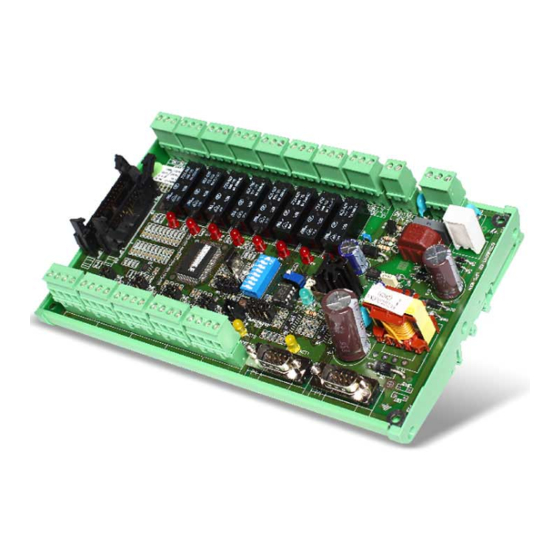
- Page 7 DESCRIZIONE Il Multi I/O è un dispositivo che permette di integrare il monitoraggio dell’UPS con la gestione di ingressi ed uscite configurabili. L’accessorio, che deve essere collegato all’UPS tramite linea seriale, gestisce otto ingressi (configurabili come ingresso digitale, ingresso analogico o sonda di temperatura) e otto uscite relè...
- Page 8 SERIAL 1 / SERIAL 3 ORTA DI COMUNICAZIONE La porta SERIAL 1 / SERIAL 3 rende disponibili due linee seriale RS-232 attraverso le quali è possibile monitorare l’UPS utilizzando i seguenti protocolli: Protocollo Baud Rate [bps] Parità Bit di stop GPSER 1200 Nessuna...
- Page 9 NGRESSI Gli otto ingressi possono essere configurati indipendentemente uno dall’altro come: Ingresso digitale; Ingresso analogico con range 0V 5V; Sonda di temperatura con range –20°C 120°C (fornita con il dispositivo). Per ogni ingresso è possibile selezionare una resistenza di pull-up o pull-down. Se un ingresso viene configurato come ingresso analogico o come sonda di temperatura è...
- Page 10 SCITE Alle otto uscite possono essere associati uno o più eventi (stati attivi) dell’UPS e/o uno o più ingressi. Gli eventi dell’UPS associabili alle uscite del dispositivo sono descritti nella tabella seguente. EVENTO STATO ATTIVO STATO NON ATTIVO DEFAULT Tensione di uscita Tensione di uscita non Uscita alimentata OUTPUT 4...
- Page 11 Se un’uscita viene associata ad uno degli eventi elencati nella tabella precedente, si avrà la commutazione del relè relativo all’uscita al verificarsi dello stato attivo. Se un’uscita viene associata ad uno degli ingressi e l’ingresso viene configurato come ingresso digitale, si avrà la commutazione del relè relativo all’uscita nel momento in cui l’ingresso si porta alto.
- Page 12 ’ ONTENUTO DELL IMBALLO Multi I/O versione “BOX” Multi I/O versione “O.F.” OPPURE Sonda di temperatura Cavo seriale Copri-connettore a tre poli + fascetta Manuale installazione + CD-Rom fermacavo (solo versione “BOX”)
- Page 13 INSTALLAZIONE ATTENZIONE TUTTE LE OPERAZIONI DESCRITTE IN QUESTO CAPITOLO DEVONO ESSERE EFFETTUATE ESCLUSIVAMENTE DA PERSONALE QUALIFICATO E ADEGUATAMENTE ADDESTRATO. ONFIGURAZIONE DEI JUMPER VERIFICARE CHE IL DISPOSITIVO NON SIA ALIMENTATO PRIMA DI AGIRE SUI JUMPER. PER IL Multi I/O VERSIONE BOX: •...
- Page 14 Per ciascun ingresso è possibile selezionare una resistenza di pull-up o pull-down agendo opportunamente sui jumper JP1, JP2, JP3, JP4, JP5, JP6, JP7 e JP8 come indicato nella tabella sottostante. La selezione della resistenza di pull-up o pull-down dovrà avvenire in base al tipo di ingresso (vedi paragrafo “Ingressi”): Digitale: selezionare come pull-up, pull-down o ingresso libero;...
- Page 15 ’ ONFIGURAZIONE DELL INDIRIZZO Per modificare l’indirizzo del dispositivo, impostare le posizioni 1÷5 del dip-switch come indicato nella tabella seguente: INDIRIZZO DIP 1 DIP 2 DIP 3 DIP 4 DIP 5 Per impostare un valore maggiore di 31, selezionare un Base address (0 = default, 32, 64, 96, 128, 160, 192, 224) tramite il programma MultiSetup.exe (vedi CONFIGURAZIONE SOFTWARE).
- Page 16 ESISTENZA DI TERMINAZIONE DEL BUS Il dispositivo viene fornito con la resistenza di terminazione già montata al suo interno (Rt=120Ω). Per inserire tale resistenza è necessario agire sulla posizione 6 del dip-switch come descritto nella tabella seguente. Rt (120Ω) DIP 6 INSERITA NON INSERITA [DEFAULT]...
- Page 17 ONNETTORI VERSIONE “BOX” (vista frontale e posteriore): 230Vac 9Vdc OUT 1 OUT 2 OUT 3 OUT 4 OUT 5 OUT 6 OUT 7 OUT 8 C NC NO C NC NO C NC NO C NC NO C NC NO C NC NO C NC NO C NC NO...
- Page 18 I COLLEGAMENTI SOTTOPOSTI A TENSIONE MAGGIORE DI 50V DEVONO ESSERE CONFORMI AI REQUISITI DI SICUREZZA. Alimentazione 230 Vac Alimentazione 9 Vdc PIN # SIMBOLO DESCRIZIONE PIN # SIMBOLO DESCRIZIONE FASE + 9 Vdc TERRA NEUTRO Morsettiera OUTPUT 1 ÷ OUTPUT 8 PIN # SIMBOLO DESCRIZIONE...
- Page 19 Morsettiera INPUT 1 ÷ INPUT 8 PIN # SIMBOLO DESCRIZIONE ALIMENTAZIONE INGRESSO 1 INGRESSO 2 Vedi “DATI TECNICI” per i carichi massimi applicabili. A seconda della morsettiera IN1 (INPUT 1) diventa IN3 (INPUT 3), IN5 (INPUT 5), IN7 (INPUT 7) A seconda della morsettiera IN2 (INPUT 2) diventa IN4 (INPUT 4), IN6 (INPUT 6), IN8 (INPUT 8) Connettore SERIAL 1 –...
- Page 20 DATI TECNICI 170 ÷ 260 Vac (50 ÷ 60 Hz) Tensione di ingresso OPPURE 9 ± 0.5 Vdc (corrente max. 600 mA) Temperatura operativa 0 ÷ 40 °C Temperatura di immagazzinamento -5 ÷ 50 °C Umidità relativa operativa 80% max. Umidità...
- Page 21 PROTOCOLLO MODBUS-JBUS UNZIONI SUPPORTATE FUNZIONI AREE DATI DESCRIZIONE FUNZIONE SUPPORTATE ACCESSIBILI (0x01) STATI LETTURA BIT (0x02) STATI (0x03) TUTTE LETTURA REGISTRI (0x04) TUTTE (0x06) SCRITTURA REGISTRO SINGOLO COMANDI 16 (0x10) SCRITTURA REGISTRI MULTIPLI COMANDI...
- Page 22 ABELLE DEGLI STATI MISURE VALORI NOMINALI E COMANDI REGISTRO STATI NUMERO INDIRIZZO NUMERO INDIRIZZO Test in esecuzione [0=No / 1=SI] Shutdown attivo [0=No / 1=SI] Batteria carica [0=No / 1=SI] Batteria in carica [0=No / 1=SI] Bypass non buono [0=No / 1=SI] Funzionamento normale [0=No / 1=SI] UPS da bypass...
- Page 23 Tensione di uscita fase L3 (stellata) 29 31 28 30 Corrente di uscita fase L1 0.1*A Corrente di uscita fase L2 0.1*A Corrente di uscita fase L3 0.1*A Corrente di picco di uscita fase L1 0.1*A Corrente di picco di uscita fase L2 0.1*A Corrente di picco di uscita fase L3 0.1*A...
- Page 24 REGISTRO VALORI NOMINALI UNITÀ NUMERO INDIRIZZO 73 77 72 76 Tensione nominale (stellata) di uscita Frequenza nominale di uscita 0.1*Hz Potenza nominale di uscita 100*VA 81 83 80 82 Capacità nominale di batteria (incluso espansioni di batteria) Rami di batteria (1 or 2) Tipo di batterie Intero...
- Page 25 REGISTRO FLAG SPECIALI (UPS SERIE SENTR) UNITÀ NUMERO INDIRIZZO Byte 1 of “s = xx..” code / Byte 2 of “s = ..xx” code Flag Byte 1 of “c = xx..” code / Byte 2 of “c = ..xx” code Flag Byte 1 of “b = xx..”...
- Page 27 NTRODUCTION Thank you for choosing our product. The accessory described in this manual is a high quality product that has been carefully designed and manufactured to guarantee optimal performance. This manual contains detailed instructions on how to install and use the product. This manual must be stored in a safe place and CONSULTED BEFORE USING THE DEVICE for proper usage instructions as well as maximum performance from the device itself.
- Page 28 NVIRONMENTAL ROTECTION Our company devotes abundant resources to analysing environmental aspects in the development of its products. All our products pursue the objectives defined in the environmental management system developed by the company in compliance with applicable standards. Hazardous materials such as CFCs, HCFCs or asbestos have not been used in this product. When evaluating packaging, the choice of material has been made favouring recyclable materials.
-
Page 29: Table Of Contents
ONTENTS DESCRIPTION SERIAL 1 / SERIAL 3 C OMMUNICATION PORT SERIAL 2 C OMMUNICATION PORT NPUTS UTPUTS IRMWARE PGRADE N THE BOX INSTALLATION UMPER SETTINGS DDRESS CONFIGURATION RS485 TERMINAL RESISTOR OFTWARE CONFIGURATION ONNECTORS TECHNICAL SPECIFICATIONS ERIAL CABLE SPECIFICATIONS MODBUS-JBUS PROTOCOL UPPORTED FUNCTION ABLES OF STATES MEASUREMENTS... -
Page 31: Description
DESCRIPTION Multi I/O has been designed to integrate the UPS monitoring with configurable input and output management. The accessory, which must be connected to the UPS through a serial interface, manages 8 inputs (configurable as digit input, analog input or temperature sensor) and 8 clean contact relay outputs (configurable in accordance with the inputs and the UPS operating mode). -
Page 32: Serial 1 / Serial 3 Communication Port
SERIAL 1 / SERIAL 3 C OMMUNICATION PORT The SERIAL 1 / SERIAL 3 communication port offers two RS-232 serial lines that can be used to monitor the UPS with the following protocol: Protocol Baud Rate [bps] Parity Stop bit GPSER 1200 Nessuna... -
Page 33: Inputs
NPUTS The eight inputs can be configured separately one from the other as: Digital input Analog input with 0V - 5V range Temperature sensor with –20°C - 120°C range (supplied with the accessory). A pull-up or pull-down resistance can be selected for each input. If an input is configured as an analog input or as a temperature sensor, a greater and/or lower threshold value can be associated with it. -
Page 34: Outputs
UTPUTS One or more UPS events (active status) and/or one or more inputs can be associated with the eight outputs. These UPS events are described in the table below: EVENT ACTIVE STATUS NON ACTIVE STATUS DEFAULT Output voltage not Output powered Output voltage present OUTPUT 4 present... -
Page 35: Firmware Upgrade
If an output is associated with one of the events listed in the table above, the relays for that output switches when an active state occurs. If an output is associated with one of the inputs that is configured as a digital input, the relay of the output in question switches when the input goes high. If an output is associated with one of the inputs that has been configured as an analog input or temperature sensor, the relay of the output in question switches when the signal on the input falls outside the predetermined values. -
Page 36: I N The Box
N THE BOX Multi I/O “BOX” version Multi I/O “O.F.” version OPPURE Temperature sensor Serial cable Three-pole connector cover and cable tie Installation manual and CD-Rom (only for the “BOX” version) -
Page 37: Installation
INSTALLATION CAUTION ALL OPERATIONS DESCRIBED IN THIS MANUAL MUST ONLY BE CARRIED OUT BY PERSONNEL WHO ARE QUALIFIED AND PROPERLY TRAINED UMPER SETTINGS MAKE SURE THAT THE DEVICE IS NOT POWERED BEFORE SETTING THE JUMPERS FOR THE Multi I/O BOX VERSION: Remove the cover, by unscrewing the screws that hold it in place, to access the jumpers. - Page 38 A pull-up or pull-down resistance can be selected for each input by positioning the jumpers JP1, JP2, JP3, JP4, JP5, JP6, JP7 and JP8 as indicated in the table below. The pull-up or pull-down resistance must be selected in accordance with the type of input (see also “Inputs”): Digital: select as pull-up, pull-down or open input Analog: leave the jumper open Temperature sensor: select a pull-up resistance for the input and connect the sensor between the...
-
Page 39: Address Configuration
DDRESS CONFIGURATION To choose the device address from 1 (default value) to 31, set the DIP-switch as indicated in the table that follows (0=OFF, 1=ON) ADDRESS DIP 1 DIP 2 DIP 3 DIP 4 DIP 5 To choose a value greater than 31, you have to select a Base Address (0-default-, 32, 64, 96, 128, 160, 192, 224) using the software MultiSetup.exe (refer to SOFTWARE CONFIGURATION). -
Page 40: Rs485 Terminal Resistor
RS485 TERMINAL RESISTOR The device is supplied with embedded terminal resistor for RS485 bus (R =120Ω). In order to insert the resistor take action on the DIP-switch no. 6 as shown in the following table: Rt (120Ω) DIP 6 INSERTED NOT INSERTED [DEFAULT] OFTWARE CONFIGURATION... -
Page 41: Connectors
ONNECTORS “BOX” VERSION (front and rear views): 230Vac 9Vdc OUT 1 OUT 2 OUT 3 OUT 4 OUT 5 OUT 6 OUT 7 OUT 8 C NC NO C NC NO C NC NO C NC NO C NC NO C NC NO C NC NO C NC NO... - Page 42 ALL CONNECTIONS SUBJECTED TO VOLTAGE OF MORE THAN 50V MUST COMPLY WITH SAFETY REGULATIONS 230 Vac Power supply 9 Vdc Power supply PIN # SYMBOL DESCRIPTION PIN # SYMBOL DESCRIPTION PHASE + 9 Vdc GROUND GROUND NEUTRAL OUTPUT 1 - OUTPUT 8 Terminal board PIN # SYMBOL DESCRIPTION...
- Page 43 INPUT 1 - INPUT 8 Terminal board PIN # SYMBOL DESCRIPTION POWER SUPPLY INPUT 1 INPUT 2 GROUND See the “TECHNICAL SPECIFICATIONS” for the maximum loads supported. Depending on the terminal board IN1 (INPUT 1) becomes IN3 (INPUT 3), IN5 (INPUT 5), IN7 (INPUT 7) Depending on the terminal board IN2 (INPUT 2) becomes IN4 (INPUT 4), IN6 (INPUT 6), IN8 (INPUT 8) SERIAL 1 –...
-
Page 44: Technical Specifications
TECHNICAL SPECIFICATIONS 170 - 260 Vac (50 - 60 Hz) Input voltage 9 ± 0.5 Vdc (max. current 600 mA) 0 – 40 °C Operating temperature -5 – 50 °C Storage temperature Relative operating humidity max.80% Relative storage humidity max. 90% 265 x 128 x 57 mm (“BOX”... -
Page 45: Modbus-Jbus Protocol
MODBUS-JBUS PROTOCOL UPPORTED FUNCTION SUPPORTED ACCESSIBLE DATA FUNCTION DESCRIPTION FUNCTION AREA (0x01) STATES BIT READING (0x02) STATES (0x03) REGISTERS READING (0x04) (0x06) SINGLE REGISTER WRITING COMMANDS 16 (0x10) MULTIPLE REGISTER WRITING COMMANDS... -
Page 46: Tables Of States Measurements Nominal Data And Commands
ABLES OF STATES MEASUREMENTS NOMINAL DATA AND COMMANDS REGISTER STATES NUMBER ADDRESS NUMBER ADDRESS Test in progress [0=No / 1=YES] Shutdown active [0=No / 1= YES] Battery charged [0=No / 1= YES] Battery charging [0=No / 1= YES] Bypass bad [0=No / 1= YES] Normal operation [0=No / 1= YES]... - Page 47 Output star voltage V3 29 31 28 30 Output current phase L1 0.1*A Output current phase L2 0.1*A Output current phase L3 0.1*A Output peak current phase L1 0.1*A Output peak current phase L2 0.1*A Output peak current phase L3 0.1*A Load phase L1 Load phase L2...
- Page 48 REGISTER NOMINAL DATA UNIT NUMBER ADDRESS 73 77 72 76 Output nominal voltage (star) Output nominal frequency 0.1*Hz Output nominal power 100*VA 81 83 80 82 Battery nominal capacity (battery expansion included) Battery benches (1 or 2) Battery type Integer 87 112 86 111 REGISTER...
-
Page 49: Ups: Commands Codes
REGISTER SPECIAL FLAGS (SENTR UPS) UNIT NUMBER ADDRESS Byte 1 of “s = xx..” code / Byte 2 of “s = ..xx” code Flag Byte 1 of “c = xx..” code / Byte 2 of “c = ..xx” code Flag Byte 1 of “b = xx..”...
Need help?
Do you have a question about the Multi I/O Series and is the answer not in the manual?
Questions and answers