Sign In
Upload
Download
Table of Contents
Contents
Add to my manuals
Delete from my manuals
Share
URL of this page:
HTML Link:
Bookmark this page
Add
Manual will be automatically added to "My Manuals"
Print this page
×
Bookmark added
×
Added to my manuals
Manuals
Brands
Frap Tools Manuals
Music Mixer
CGM
Manual
Frap Tools CGM Manual
A single, comprehensive guide to frap tools’ modules
Hide thumbs
Also See for CGM
:
Manual
(107 pages)
,
User manual
(7 pages)
,
Manual
(82 pages)
1
2
Table Of Contents
3
4
5
6
7
8
9
10
11
12
13
14
15
16
17
18
19
20
21
22
23
24
25
26
27
28
29
30
31
32
33
34
35
36
37
38
39
40
41
42
43
44
45
46
47
48
49
50
51
52
53
54
55
56
57
58
59
60
61
62
63
64
65
66
67
68
69
70
71
72
73
74
75
76
77
78
79
80
81
82
83
84
85
86
87
88
89
90
91
page
of
91
Go
/
91
Contents
Table of Contents
Bookmarks
Table of Contents
Table of Contents
Safety and Warranty
Before Starting
Connecting the Power
Mounting the Module
Warm-Up and Working Temperature
Interfaces
Arrows (Input, Output)
Square and Round Shapes
Lines (Solid, Dotted, Dashed)
Color Coding
Combinations
Cgm - Creative Mixer
Philosophy and Design
System Setup (Linking)
Master to Group(S)
Group to Channel(S)
Group Jumpers Configurations
Channel
Main VCA & Direct out
Sends
Pan, Fader and Other Controls
Group
Sends
Returns
Group Output
Fader and Other Controls
The Safe solo Function
Master
The PFL Function
CGM Mixer Tips
Stereo Inputs
More than 2 Send/Returns Per Channel
Serial Send/Return (and Feedbacks)
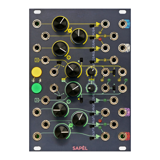
Sapèl
Philosophy and Design
Noise Outputs
Voltage Sampling
Internal Clock and Clock Modulation
External Clock
Clock MIX
Manual Sampling
External Gate Sampling
Clock Outputs (Main and Random)
Random Voltages
Non-Quantized Random Voltages
Quantized Random Voltages
Fluctuating Random Output and Global Rate of Change (Random Clock Density Control)
Probability Distribution (Stored Random Voltages)
Fumana
Philosophy and Design
Spectral Transfer: a Brief History
Panel Overview
Audio Inputs
Audio Outputs
Audio Processing and Modulation Path
Faders and CV
Macro Spectral Editing
Tilt
Parametric Scanning
Spectral Transferring: Modulation Filters and Envelope Followers
The 'Unvoiced' Section
Filter Design
Patch Examples
16-Band Spectral Transfer
Dual 8-Band Spectral Transfer
Hybrid Spectral Transfer
Vocoder-Like Behavior
Falistri
Philosophy and Design
Function Generators
Times
Shapes
Trig and Modes
Green Alternative Retrig (on Rest)
Outputs
Additional Generator Features
Quadrature
Max
Adsr
Function Processors
Dual Cascaded Frequency Divider
Four-Quadrant Multiplier
Amplitude Modulation & Ring Modulation
Quadrants)
Trimming
Linear Slew Limiter
Usta
Quick Start
Philosophy and Design
Architecture
Tempo Management
Basic Editing and Visual Feedback
Editing Projects − Project Menu
Editing Tracks − Track Menu
Clock Settings
Editing, Playing and Looping Patterns
Editing Stages
Length
Maintain Pattern Length on Variation
CV Layers
Red CV Layer: Value
Green CV Layer: Variation Index
Blue CV Layer: Variation Range
CV Stage Colors
USTA Slide Vs FALISTRI Slew
Gate Layers
Red Gate Layer: Value
Green Gate Layer: Variation Index
Blue Gate Layer - Variation Range
Gate Stage Colors
Quick Editing
Set All and Shift All
Coarse and Fine
Combining the Buttons
Performing
Play/Pause, Reset and Master Track Settings
Master Track
Play/Pause
Reset
Stage Loop
Infinite Stage Loop
Song Mode
Pattern to Song While Playing (and Vice Versa)
Live Performance Tools: Pattern Recall
Full Pattern Recall
Pattern MIX
Mute
Mute Track
Mute Channel
Hold
Advanced Editing
Composition Mode
Use an External CV/Gate Keyboard
Store Pattern: Last Played or Last Full
Rotate Pattern
Cloning
Clone a Stage
Clone a Structure
Clone a Layer
Layer Cross-Cloning
Clone a Pattern
Clone a Track
Quick Track Initialization
Quick Song Initialization
External Controls
Clock Input
Auxiliary Trig/Gate Input
Reset
Run
External CV
Pitch Shift
Root Shift
Gate Shift
Stage Shift
Vari Shift (Variation Shift)
Pattern Shift
Phase Shift
Additional Operations
Select CV Mode (Raw or Pitch)
CV Range
Gate Width
Swing
Current Stage Data
Playing in Tune
Root & Scale - Dynamic Quantization
Microtonalities
Custom Scales
Set the Reference Note
Custom Temperaments
Absolute or Relative Temperaments
LED Pitch Tables
Additional Maintenance
Remove / Insert the SD Card
Remove the SD Card
Insert the SD Card
Analog Trimming
Project Management and Backups
Firmware Update
Charts
Project Menu
Track Menu
Project Hierarchy
Scale Tables
Change Log
Brenso
Philosophy, Design and Signal Flow
Frequency
Oscillators
Fine and Coarse Tuning
Coarse Frequency Lock
V/Oct and Integrator
Frequency Modulation
FM Routing
Sync
Lock
Flip Sync
Timbre
Triangle Shaper
Pulse Shaper
Pulse-Width Modulation (PWM)
Waveshaper
Wavefolder
Sources
Folding
Symmetry
Ping
Timbre Modulation Bus
Amplitude
Amplitude Modulation and Ring Modulation
Trimmers
Accessible Trimmers
Coarse Frequency
Sine Wave Symmetry
Sawtooth Wave Symmetry
Exponential FM Zero
Triangle Waveshaper Shape
Wavefolder Symmetry
Four-Quadrant Multiplier
Comparator
Gain
Base
Symmetry
Simple Signal Flow
Design
Design
Technical Details
Flow Charts
Cgm
Sapèl
Cgm Creative Mixer Vca Curves
Fumana Transfer Function
Specifications
CGM − Creative Mixer
Sapèl
Falistri
Fumana
Usta
Brenso
What's in the Box
List of Revisions
Advertisement
Quick Links
1
Table of Contents
2
Arrows (Input, Output)
3
Interfaces
4
Color Coding
5
Falistri
6
Brenso
Download this manual
MANUALONE
A Single, Comprehensive Guide to Frap Tools' Modules
Table of
Contents
Previous
Page
Next
Page
1
2
3
4
5
Advertisement
Table of Contents
Need help?
Do you have a question about the CGM and is the answer not in the manual?
Ask a question
Questions and answers
Related Manuals for Frap Tools CGM
Music Mixer Frap Tools CGM Manual
(107 pages)
Recording Equipment Frap Tools CGM Manual
(82 pages)
Recording Equipment Frap Tools CGM Manual
Creative mixer (13 pages)
Recording Equipment Frap Tools 333 User Manual
Pro audio sum & distribution (7 pages)
Music Mixer Frap Tools FALISTRI Manual
A single, comprehensive guide to frap tools’ modules (91 pages)
Music Mixer Frap Tools BRENSO Manual
A single, comprehensive guide to frap tools’ modules (91 pages)
This manual is also suitable for:
Sapel
Fumana
Falistri
Usta
Brenso
333
...
Show all
321
F-can0-mx
F-gru0-mx
F-sap0-rg
F-fum0-sp
F-fal0-de
F-ust0-sq
F-bre0-os
F-3330-sm
F-3210-ta
Table of Contents
Print
Rename the bookmark
Delete bookmark?
Delete from my manuals?
Login
Sign In
OR
Sign in with Facebook
Sign in with Google
Upload manual
Upload from disk
Upload from URL


Need help?
Do you have a question about the CGM and is the answer not in the manual?
Questions and answers