Chapters
Table of Contents

Subscribe to Our Youtube Channel
Summary of Contents for BMW Motorrad X2City
- Page 1 IMPORTANT READ CAREFULLY BEFORE USE KEEP SAFE FOR LATER REFERENCE BMW Motorrad TRANSLATION OF THE ORIGINAL OPERATING INSTRUCTIONS E-Scooter X2City KW074-DAMS99, KW074-DBMS99, KW074-DCMS99, KW074-DDMS99 877-00113_1.2_06.08.2018...
- Page 2 Copyright © KETTLER Alu-Rad GmbH Distribution or reproduction of these operating instructions and utilisation or communication of their content is prohibited unless expressly approved. Any infringement will render the offender liable for compensation. All rights reserved in the event that a patent, utility model or industrial design is registered.
-
Page 3: Table Of Contents
Table of contents About these instructions Manufacturer Laws, standards and directives Other valid documents Subject to change Language Identifying 1.6.1 Operating instructions 1.6.2 E-Scooter For your safety 1.7.1 Instruction, training and customer service 1.7.2 Basic safety notes 1.7.3 Warnings 1.7.4 Safety markings For your information 1.8.1... - Page 4 Table of contents Technical data E-Scooter USB port Battery Control panel with display Tightening torque Transportation, storage and assembly Transportation Storing 5.2.1 Break in operation 5.2.1.1 Preparing a break in operation 5.2.1.2 Carrying out break in operation Assembly 5.3.1 Unpacking 5.3.2 Scope of delivery Commissioning...
- Page 5 Table of contents Electrical drive system 7.5.1 Switching on the drive system 7.5.2 Switching off the drive system Control panel with display 7.6.1 Using the driving light 7.6.2 Selecting the maximum speed level 7.6.3 Functional displays 7.6.3.1 Changing the journey information and system functions 7.6.3.2 Resetting all the saved journey information 7.6.4...
- Page 6 Table of contents Recycling and disposal Appendix 10.1 EC declaration of conformity 10.2 Spare parts 10.3 List of tables 10.4 Table of figures 10.5 Index 877-00113_1.2_06.08.2018...
-
Page 7: About These Instructions
About these instructions About these instructions Read these operating instructions before commissioning the e-scooter, so that you can use all the functions correctly and safely. They are not a substitute for personal training by the supplying specialist dealer. The operating instructions are an integral part of the e-scooter. -
Page 8: Laws, Standards And Directives
About these instructions Laws, standards and directives These operating instructions comply with the essential requirements from: • the Machinery Directive 2006/42/EC, • the Radio Equipment Directive 2014/53/EC, • EN ISO 12100:2010 Safety of machinery – General principles of design – Risk assessment and reduction, •... -
Page 9: Subject To Change
About these instructions Subject to change The information contained in these operating instructions are the approved technical specifications at the time of printing. Any significant changes are included in a new issue of the operating instructions. Any changes which are not relevant to safety are published on the following website: http//www.kettler-alu-rad.de Language... -
Page 10: Identifying
Table 1: Identification number of the operating instructions 1.6.2 E-Scooter These BMW Motorrad brand operating instructions refer to the model year 2018. The production period is from January 2018 to December 2018. They are issued in January 2018. The operating instructions are an integral part of the... -
Page 11: For Your Safety
About these instructions For your safety The e-scooter's safety concept comprises four elements: • rider and/or user instruction, and e-scooter maintenance and repair by the specialist dealer, • the chapter on general safety, • the warnings in these instructions and •... -
Page 12: Basic Safety Notes
About these instructions 1.7.2 Basic safety notes These operating instructions have a chapter with general safety notes [ Chapter 2, page 15. The chapter stands out because of its grey background. 1.7.3 Warnings Hazardous situations and actions are marked with warnings. -
Page 13: Safety Markings
About these instructions 1.7.4 Safety markings The following safety markings are used on the e- scooter's type plates: General warning Adhere to the instructions for use Table 4: Safety markings on the product For your information 1.8.1 Language conventions The following terms are used for better legibility: Term Meaning Operating... -
Page 14: Instructions For Actions
About these instructions 1.8.2 Instructions for actions Instructions for actions are structured in accordance with the following pattern: Requirements (optional) nstruction for action Result of the action (optional) 1.8.3 Information on the type plates Alongside warnings, the products' type plates also contain other important information relating to the e-scooter and the charger. -
Page 15: Table 8: Information On The Type Plate
About these instructions Read the instructions Separate collection of electrical and electronic devices Separate collection of batteries Must not be thrown into fire (burning prohibited) Must not be thrown into water (immersed) Device of protection class II Only suitable for use indoors Fuse (device fuse) EU conformity Recyclable material... -
Page 16: Type Plate
About these instructions Type plate The type plate is situated on the frame. The type plate features the following information: Ke ler Alu-Rad GmbH Typ: BMW X2City Baujahr: 2018 FIN-Nr. AA 70757807 ABE.-Nr. …………… Zul. Gesamtgewicht: 150 kg Abschaltgeschwindigkeit: 20 km/h... -
Page 17: Safety
Safety Safety Requirements for the rider The physical, the mental and motor abilities of the rider must be sufficient for riding on public roads. Legal guardians hold sole responsibility for determining whether minors are capable of using the e-scooter. Personal protective equipment It is recommendable to wear a suitable safety helmet, gloves and knee and elbow guards. -
Page 18: Improper Use
Safety Improper use Failure to adhere to the proper use poses a risk of personal injury and material damage. The e-scooter is not suitable for use under the following circumstances: • after manipulation to the electrical drive system • riding with a damaged or incomplete e-scooter •... -
Page 19: User
Safety 2.5.2 User The user has the duty of care and responsibility for scheduling these measures and checking that they are implemented. The user: • makes these operating instructions available to the rider for the duration of use of the e-scooter. If necessary, they can translate the operating instructions into a language which the rider understands. -
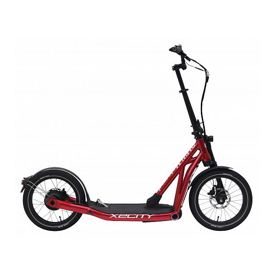
Page 20: Description Overview
Description Description Overview Figure 2: E-scooter, from right Front wheel Front mudguard Fork Headlight Handlebars Stem Frame Vehicle ID no. Battery compartment lock Footboard Pedal Rear mudguard Reflector, front and rear Rear light Rear wheel Kickstand Battery compartment 877-00113_1.2_06.08.2018... -
Page 21: Handlebars
Description Handlebars Figure 3: Detailed view of e-scooter from rider position Rear brake lever Front brake lever Bell Control panel with display 877-00113_1.2_06.08.2018... -
Page 22: Wheel And Fork
Description Wheel and fork Figure 4: Components of the wheel, example of front wheel Tyre Valve Fork Spoke 3.3.1 Valve Each wheel has a Schrader valve. It is used to fill the tyre with air. There is a valve cap on each valve. The screw-on valve cap keeps out dust and dirt. -
Page 23: Brake System
Description Brake system The e-scooter's brake system comprises a hydraulic disc brake on both the front and rear wheel. Figure 5: E-scooter brake system with disc brake Handlebars with brake levers Brake caliper with brake linings Brake disc Rear wheel brake disc Front wheel brake disc The brake disc is permanently connected to the wheel hub on e-scooters with a disc brake. -
Page 24: Drive System
Description Drive system The e-scooter is propelled by leg muscle power pushing on the ground and can be ridden in the same way as a conventional kick scooter. The e-scooter also has an integrated electric drive system. The electric drive system is made up of seven components: Figure 6: Diagram of electric drive system... -
Page 25: Battery
Description The motor switches off automatically after 5 m if the rider no longer stands on the pedal, a brake is applied, the temperature is outside the permitted range, there is an overload, or the shut-off speed of 20 km/h has been reached. -
Page 26: Operating And Charge Status Indicator
Description The e-scooter has a battery compartment underneath the footboard, which contains the battery. Figure 7: Integrated battery details Charging port Handle On-Off button (battery) Operating and charge status indicator 3.5.1.1 Operating and charge status indicator The five blue LEDs in the operating and charge status indicator signal the battery charge status when the battery is switched on. -
Page 27: Control Panel With Display
Description 3.5.3 Control panel with display The control panel with display controls the drive system with five operating elements, and displays the journey data. Operating temperature -10 °C–65 °C Storage temperature -20 °C–85 °C Protection class IP 65 Table 10: Technical data for the control panel with display The control panel with display has four buttons, a joystick and a USB port. -
Page 28: Usb Port
Description 3.5.3.1 USB port There is a USB port underneath the rubber cover at the bottom edge of the control panel with display.The USB port is used as an interface for connecting a fault diagnostics device and for the use of compatible USB devices Interface Micro USB standard 2.0 Full Speed... -
Page 29: Display
Description 3.5.3.2 Display The control panel with display has five screen displays: km/h Figure 9: Overview of the control panel with display Display of maximum speed levels Function display Battery charge status indicator Bluetooth symbol Driving light symbol Table 13: Overview of the control panel with display 877-00113_1.2_06.08.2018... -
Page 30: Table 14: System Functions
Description Maximum speed levels When the rider steps on the pedal, the motor is activated until the speed set by the rider has been reached. Six speed levels are available. Function display The function display shows different information and functions: •... -
Page 31: Table 15: Journey Information
Description Journey information The main screen of the control panel with display shows the current speed in km/h. The displayed screen can be changed using the joystick. Tour Distanz Figure 10: Example of the tour distance page with e-scooter symbol (1) Screen Symbol Function... -
Page 32: Pedal
Description ystem message The drive system monitors itself continuously and if an error is detected, it is indicated by a system message. The system may switch off automatically depending on the type of error. There is a table of system messages in the appendix. -
Page 33: Table 16: E-Scooter Technical Data
Technical data Technical data E-Scooter Transportation temperature 5 °C–25 °C Storage temperature 5 °C–25 °C Ideal storage temperature 10 °C–15 °C Operation temperature 5 °C–35 °C Working environment temperature 15 °C–25 °C Charging temperature 10 °C–30 °C Power output/system 250 W (0.25 kW) Shut-off speed 20 km/h for Germany/... -
Page 34: Table 18: Battery Technical Data
Technical data Battery Transportation temperature 5 °C–25 °C Storage temperature 5 °C–25 °C Ideal storage temperature 10 °C–15 °C Charging ambient temperature 10 °C–30 °C Table 18: Battery technical data Control panel with display Operating temperature -10 °C–65 °C Storage temperature -20 °C–85 °C Protection class IP 65... -
Page 35: Figure 11: Screw Connections On The Handlebars
Technical data Tightening torque Figure 11: Screw connections on the handlebars Quantity and screws maximum tightening torque 2 x M7 10.0 Nm 4 x M7 10.0 Nm Figure 12: Screw connections on the front wheel and the lower fork, from the left Quantity and screws maximum tightening torque... -
Page 36: Figure 13: Screw Connections On The Front Wheel And The Lower Fork
Technical data Figure 13: Screw connections on the front wheel and the lower fork, from the right Quantity and screws maximum tightening torque 1 x M6 x 30 as far as it will go 1 x M6 2.0 Nm 2 x M5 x 16 2.6 Nm 1 x M8 15.0 Nm... -
Page 37: Figure 15: Screw Connections On The Rear Wheel, From Below
Technical data Figure 15: Screw connections on the rear wheel, from below Quantity and screws maximum tightening torque 2 x M5 x 12 0.8 Nm 4 x M6 x 25 10.0 Nm 4 x M5 x 12 4.0 Nm 2 x M6 x 20 10.0 Nm 2 x M5 x 12 0.8 Nm... -
Page 38: Figure 17: Footboard Screw Connections, From Below
Technical data Figure 17: Footboard screw connections, from below Quantity and screws maximum tightening torque 2 x M8 x 20 6.0 Nm 2 x M5 x 16 2.6 Nm 2 x STS KN1038 5 x 20 0.2 Nm 4 x STS Kn1038 4 x 20 2.0 - 2.1 Nm 2 x M5 x 12 0.8 Nm... - Page 39 Transportation, storage and assembly Transportation, storage and assembly Transportation U n i n t e n t i o n a l a c t i v a t i o n CAUTION The rear wheel hub motor can be activated by operating the pedal while the rear wheel is turning.
-
Page 40: Table 21: Storage Temperature For The Battery, E-Scooter And
Transportation, storage and assembly Storing R i s k o f f i r e a n d e x p l o s i o n d ue t o h i g h CAUTION t e m p e ra t u r e s Excessively high temperatures damage the battery. - Page 41 Transportation, storage and assembly 5.2.1.1 Preparing a break in operation Remove the battery from the e-scooter. Charge the battery to around 60% (three to four LEDs of the charge status indicator light up). The e-scooter needs to be cleaned with a damp cloth and preserved with wax spray.
-
Page 42: Table 22: Working Environment Temperature
Transportation, storage and assembly Assembly Assemble the e-scooter in a clean and dry environment. The working environment temperature should be between 15 °C and 25 °C. Working environment temperature 15 °C–25 °C Table 22: Working environment temperature Universal tools, a torque spanner with an operating range of 0.2 Nm to 18 Nm and the special tools, as recommended by KETTLER Alu-Rad GmbH, must be... - Page 43 Transportation, storage and assembly Move the handlebars and stem into the functional position. Move the brake handles, control panel with display and the bell into position. Screw all the components in place. Check the entire cable harness to make sure that it is routed properly: •...
- Page 44 Transportation, storage and assembly 5.4.1 Checking the battery Fire and explosion caused by incorrect charger CAUTION Batteries which are charged with an unsuitable charger, may become internally damaged. This may result in fire or an explosion. Only ever use the battery with the supplied charger. ...
-
Page 45: Table 23: Handlebars Clamping Screw Maximum Tightening Torque
Adjusting X2City to rider Adjusting e-scooter to rider Setting the handlebars Crash caused by incorrectly set clamping force CAUTION Excessively high clamping force will damage the quick release and cause it to lose its function. Insufficient clamping force will cause a detrimental transmission of force. -
Page 46: Figure 18: Closed Clamping Lever (1) With Knurled Nut (2) And Locking
Adjusting X2City to rider Figure 18: Closed clamping lever (1) with knurled nut (2) and locking screw (3) on the stem 6.1.1 Checking the clamping force of the quick release Open and close the stem quick release. The clamping force is sufficient if the clamping... -
Page 47: Figure 19: Brake Lever (1) With Setting Screw (2)
Adjusting X2City to rider Setting the grip distance of the brake lever The specialist dealer can adjust the brake lever to the rider's grip distance. Set the grip distance by turning the setting screw (2) on the brake lever with a Torx T25. - Page 48 Operation Operation Crash caused by loose clothing CAUTION Laces, scarves and other loose items may become entangled in the spokes on the wheels and the brake discs. Such damage may cause you to fall from the vehicle and injure yourself. ...
- Page 49 Operation Heat or direct sunlight can cause the tyre pressure to NOTICE increase above the permitted maximum pressure. This can destroy the tyres. Never park the e-scooter in the sun. On hot days, regularly check the tyre pressure and adjust it as necessary.
- Page 50 Operation Before each ride Crash caused by difficult-to-spot damage CAUTION After a crash, accident or if the e-scooter falls over, there may be damage which is hard to detect, e.g. to the brake system or the frame. Such damage may cause you to fall from the vehicle and injure yourself.
- Page 51 Operation Check list before each ride Check that the e-scooter is complete. Check that the lighting, reflector and brake, for instance, are sufficiently clean. Check that the mudguards are securely installed. Check that the front and rear wheels run true. This is particularly ...
- Page 52 Operation Using the kickstand Crash caused by a lowered kickstand CAUTION The kickstand does not fold up automatically. There is a risk of crashing if riding with the kickstand lowered. Raise the kickstand completely before the ride. The heavy weight of the e-scooter may cause the NOTICE kickstand to sink into soft ground and the e-scooter may topple and fall over.
-
Page 53: Figure 20: Closed Clamping Lever (1) With Knurled Nut (2) And Locking
Operation Folding Never crush or bend electric cables or brake cables NOTICE when folding the e-scooter. 7.3.1 Folding the e-scooter The e-scooter is folded in four steps. Switch off the electric drive system. Remove the battery if necessary ... -
Page 54: Figure 21: Frame, With The Frame Clamping Lever Open (1), Locking
Operation 7.3.1.2 Folding the stem Press the frame locking lever downwards (1) while pushing the integrated locking lever upwards at the same time. Pull the locking bolt forward (2). Pivot in the frame as far as it will go (3). Figure 21: Frame, with the frame clamping lever open (1), locking bolt pushed forward (2) and stem half open (3) -
Page 55: Figure 22: Frame, With The Stem Half Open (1), Locking Bolt Pushed
Operation 7.3.2.1 Folding out the stem Completely fold out the frame. Push the securing pin into the frame (1). Close the frame clamping lever. The frame clamping lever rests on the limit stop. The frame locking lever holds the frame clamping lever. The frame clamping lever is closed. - Page 56 Operation Battery Risk of fire and explosion due to faulty battery WARNING The safety electronics on damaged or faulty batteries may fail. The residual voltage can cause a short circuit. The batteries may self-ignite and explode. Remove batteries with external damage from service immediately and never charge them.
- Page 57 Operation Fire and explosion caused by short circuit CAUTION Small metal objects may jumper the electrical connections of the battery. The batteries may self- ignite and explode. Keep paper clips, screws, coins, keys and other small parts away from the battery and do not insert them into the battery.
-
Page 58: Figure 23: Open (2) The Battery Compartment Cover (1) And The
Operation If a key is left inserted when riding or transporting the NOTICE e-scooter, it may break off or the lock may open accidentally. Remove the key from the battery lock immediately after use. We recommend that you attach the key to a key ring. - Page 59 Operation 7.4.2 Inserting the battery Open the battery lock with the key. Open the battery compartment cover. Place the battery in the frame with the contacts facing in the direction of travel, taking hold of the battery by the handle. ...
- Page 60 Operation 7.4.3 Charging the battery Fire caused by overheated charger CAUTION The charger heats up when charging the battery. In case of insufficient cooling, this can result in fire or burns to the hands. Never use the charger on a highly flammable surface (e.g.
- Page 61 Operation Connect the mains plug of the charger to a normal domestic, grounded socket. 230 V, 50 Hz Connection data Connect the charging cable to the battery's charging port. The charging process starts automatically. During the charging process the operating and charge status indicator indicates the charge status.
- Page 62 Operation Risk of fire and explosion caused by CAUTION damaged batteries. The safety electronics on damaged or faulty batteries may fail. The residual voltage can cause a short circuit. The batteries may self-ignite and explode. If the battery becomes deformed or begins to smoke, keep at a safe distance, disconnect the power supply at the socket, and notify the fire service immediately.
- Page 63 Operation Electrical drive system 7.5.1 Switching on the drive system A sufficiently charged battery has been inserted into the e-scooter. The battery is firmly in place. The key has been removed. After switching off, the drive system shuts down. It is possible to switch back on immediately.
- Page 64 Operation Control panel with display 7.6.1 Using the driving light To switch on the driving light, the drive system has to be switched on already. Press the headlight button briefly. The driving light is switched on, and the driving light symbol is displayed.
- Page 65 Operation 7.6.3.2 Resetting all the saved journey information Move the joystick to the right again until the required journey information TOUR DISTANZ is displayed. Move the joystick downwards until the desired journey information R E SE T is displayed. Press the joystick down again and RESET will be highlighted in grey.
- Page 66 Operation 7.6.5.1 Activating Bluetooth connectivity Select the item of journey information B L U E T O O T H . Select the device type to be used for data exchange. Go to the main screen. Connect the Bluetooth device to the control panel. For this, follow the instructions on the Bluetooth device.
- Page 67 Operation Pedal 7.7.1 Using the pedal Use your foot to accelerate the e-scooter to at least 6 km/h. Use your left or right heel to step on the pedal. The motor is activated briefly and provides assistance to the pedalling movement for 5 m. ...
- Page 68 Operation Brakes Crash caused by incorrect use CAUTION Handling the brake improperly can lead to loss of control or crashes, which may result in injuries. Practice braking and emergency braking before using the e-scooter in public spaces. Shift your weight back and down as far as possible. Crash caused by wet conditions CAUTION The tyres may slip on wet roads.
- Page 69 Operation If the rider steps on the pedal with his/her heel, the drive force of the motor is switched off for 5 m. The drive system switches off immediately when braking. 7.8.1 Using the brake Pull the brake levers until the desired speed has been reached.
- Page 70 Maintenance Maintenance Cleaning check list before each Cleaning the plug contacts charging process Cleaning the battery once a month Basic cleaning and preservation of all at least every six components months at least every six Clean the charger months Maintenance check list ...
- Page 71 Maintenance Cleaning and servicing Unintentional activation CAUTION The rear wheel hub motor can be activated by operating the pedal while the rear wheel is turning. There is a risk of injury. Remove the battery before cleaning. The following servicing measures must be carried out regularly [ Check list, page 68].
- Page 72 Maintenance 8.1.3 Basic cleaning and preservation Crash caused by brake failure CAUTION The braking effect may be unusually weak temporarily after cleaning, servicing or repairing the e-scooter. Such damage may cause you to fall from the vehicle and injure yourself. ...
- Page 73 Maintenance Maintaining Unintentional activation CAUTION The rear wheel hub motor can be activated by operating the pedal while the rear wheel is turning. There is a risk of injury. Remove the battery before maintenance. The following maintenance measures must be carried out regularly [ Check list, page 68].
- Page 74 Maintenance 8.2.3 Electrical cables and brake cables Check all visible electrical cables and hydraulic lines for damage. If, for example, hydraulic lines are cracked or buckled, the e-scooter will need to be removed from service until the cables have been replaced.
- Page 75 Maintenance Service Unintentional activation CAUTION The rear wheel hub motor can be activated by operating the pedal while the rear wheel is turning. There is a risk of injury. Remove the battery before the service. Crash caused by material fatigue CAUTION If the service life of a component has expired, the component may suddenly fail.
- Page 76 Maintenance Adjusting and repairing Unintentional activation CAUTION The rear wheel hub motor can be activated by operating the pedal while the rear wheel is turning. There is a risk of injury. Remove the battery before adjusting and repairing. 8.4.1 Using original parts only The individual e-scooter parts have been carefully selected and matched to one other.
-
Page 77: Figure 24: Schrader Valve With Rim Nut (1)
Maintenance 8.4.2 Adjusting the tyre pressure It is recommendable to use an air pump with a pressure gauge. The operating instructions for the air pump must be adhered to. Unscrew and remove the valve cap. Connect the air pump. ... - Page 78 Maintenance 8.4.3 Replacing the lighting Only use components of the respective power class for replacement. 8.4.4 Setting the headlight The headlight must be positioned, so that its light beam meets the road 10 m in front of the e-scooter. 8.4.5 Repair by the specialist dealer Special knowledge and tools are required for many...
- Page 79 Maintenance First aid Proceed as follows if the control panel with display and/or the drive system fail to start up: Check whether the battery is switched on. If not, start the battery. Contact specialist dealer if the charge status indicator LEDs do not light up.
- Page 80 Maintenance 8.5.1 First aid for system messages F i re a n d e x p l os i o n d ue t o f a u l t y b a t t e ri e s WARNING The safety electronics on damaged or faulty batteries may fail.
- Page 81 Maintenance 8.5.1.1 Specific error eradication If the following system messages appear, the rider must act as follows: Error Remedy Charge the battery. Charge the battery. Incorrect charger. Use the supplied charger for charging. 40, 41, 44 Overcurrent detected and motor overheating ...
- Page 82 Recycling and disposal Recycling and disposal Risk of fire and explosion WARNING The safety electronics on damaged or faulty batteries may fail. The residual voltage can cause a short circuit. The batteries may self-ignite and explode. Remove batteries with external damage from service immediately and never charge them.
- Page 83 Recycling and disposal The e-scooter, battery, control panel with display and charger are recyclable. You must dispose of and recycle them separately from the domestic waste in compliance with applicable statutory regulations. Separate collection and recycling saves reserves of raw materials and ensures that all the regulations for protection of health and the environment are adhered to when recycling the product and/or the battery.
- Page 84 Appendix Appendix 10.1 EC declaration of conformity Translation of the original EC declaration of conformity The manufacturer: KETTLER Alu-Rad GmbH Abteilung Motorisierung Longericher Str. 2 50739 Köln Germany hereby declares that the electrically power assisted cycles of types: KW074-DAMS99, KW074-DBMS99, KW074-DCMS99 and KW074-DDMS99 year of manufacture 2017 and year of manufacture 2018, comply with all applicable requirements of Machinery Directive 2006/42/EC.
-
Page 85: Table 25: Spare Parts
Brake disc P0HTPB1 MAGURA adapter QM43 ISV 160 P0HY6F3 MAGURA front wheel brake MT NEXT 2 4 C P0HTPA9 Brake linings (blue) P0VGRO4 Fork stanchion X2CITY P0K8NC7 Fork bridge rubber wedge, bottom P0HJMO6 Lower fork bridge P0DW3X1 Headset clamp P8U7843 Headset bearing, bottom, 1.5"... - Page 86 P0NF3U4 Tail lamp holder P0NF3U0 SUPERNOVA rear light M99 P0DT1O8 Z large reflector P0HM8A3 Trapezoidal mount, rear mudguard P0H6NZ7 Frame X2CITY P09HGA2 Footboard well P0NF3T0 Footboard cover P0NF3T7 Battery compartment cover seal P0NKPA3 EPDM 25SHORE A Battery lock Make M0103 0575 100...
- Page 87 Article number MARQUARDT pedal sensor P09XCI3 Kickstand X2CITY P0FCXG5 Rechargeable battery X2CITY P0DR5Y4 Pedal X2CITY P0DLSW4 Magnetic pedal holder X2CITY P0B3QP8 Collar bushing IGUS JVFM-0810-10 P0GXMR8 Collar bushing IGUS WFM-0810-07 P0B1PZ9 Pedal bearing bolt X2CITY P0B1QE6 Leg spring Pedal X2CITY...
- Page 88 List of tables 10.3 List of tables Table 1: Identification number of the operating instructions, 8 Table 2: Type number and model categorisation, 8 Table 3: Meanings of the signal words, 10 Table 4: Safety markings on the product, 11 Table 5: Simplified terms, 11 Table 6:...
- Page 89 Table of figures 10.4 Table of figures Figure 1: Type plate, example, 14 Figure 2: E-scooter, from right, 18 Figure 3: Detailed view of e-scooter from rider position, 19 Figure 4: Components of the wheel, example of front wheel, 20 Figure 5: E-scooter brake system with disc brake, 21 Figure 6:...
- Page 90 Index 10.5 Index Charger, Hub, 20 Area of use, 12 - disposing of, 81 Assembly, 40 Charging port, 24 Journey information, 29 Checklist, - resetting, 63 before each ride, 49 Basic cleaning and - switching, 62 Cleaning, 68 preservation, Joystick, 25 Maintenance, 68 cleaning and servicing, 70 Commissioning, 40...
- Page 91 Index Speed level, 28 - selecting, 62 Down button, 25 Up button, 25 Speed, Average, 29 Shut-off speed 31 Spoke, 20 Stand, see kickstand Stem, 18 - folding out, 53 - folding, 52 Storing, 38 System function, 28 System message, 30 First aid, 78 Table, 79 Technical data 31...
- Page 92 Text and images: KETTLER Alu-Rad GmbH Longericher Straße 2 50739 Köln, Germany Translation: Tanner Translations GmbH+Co Markenstraße 7 40227 Düsseldorf, Germany Operating instructions: 877-00113 1.2 06.08.2018...
- Page 93 www.kettler-alu-rad.de KETTLER Alu-Rad GmbH Longericher Straße 2 50739 Köln, Germany Tel.: +49 6805 6008 0 Fax: +49 6805 6008 3098 E-mail: info@kettler-alu-rad.de YOUR SPECIALIST DEALER...
Need help?
Do you have a question about the X2City and is the answer not in the manual?
Questions and answers