Advertisement
Quick Links
B
oiler room components
0454EN October 2013
F
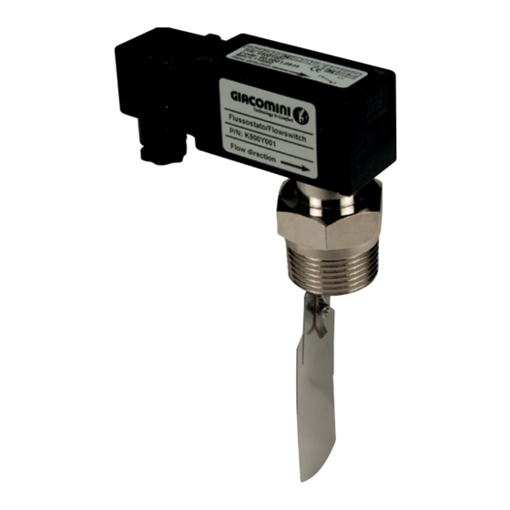
K500
low switch
Description
The flow switch K500 is used to control the flow in the pipes of the heating
and/or conditioning system. The flow switch is fitted as standard with three
blades for use in pipes from DN25 to DN80, plus a fourth blade for pipes with
a diameter of (or greater than) DN100. The device is designed in such a way as
to ensure hermetic separation of the mechanical part from the electric part.
The electric head can be removed and replaced.
Operation
When inserted in the pipe, the blade movement is proportional to the flow
that strikes it; the movement is mechanically transmitted to a microswitch
that activates or deactivates an electric contact (figure 2). The sensitivity of
the flow switch can be adjusted via the setting screw (figure 1). A particular
feature of the device is its low load loss.
Main characteristics
• For use in pipes DN25÷200
• Body in nickel-plated brass
• Blades in steel
• Protection blower in NBR
• Spring in steel
• SPDT microswitch
• Contact capacity 250 V - 5 A
• Electric connection by means of DIN 43650A connector
• Protection degree IP65
• Weight 350 g
Technical data
• Max. fluid temperature: 110 °C
• Max. working pressure: 25 bar
• Average loss of pressure: 0,15 bar (at maximum capacity)
• Precision: ±15%
Installation
The number of blades to be used depends on the pipe diameter (D) and the
intervention capacity.
DN
[mm]
25
32
40
50
65
K500
80
100
150
200
Table 1 - Number of blades to use
(*) These data refer to horizontal assembly and decreasing flow with fluid = water
Figure 1 - Geometry of the flow switch / pipe coupling.
Intervention capacity
Maximum capacity
Setting range (*)
[m
/h]
3
[m
/h]
3
3,6
0,9 ÷ 1
6
2,3 ÷ 2,7
9
2,8 ÷ 3,4
6,5 ÷ 7,5
15
1,9 ÷ 2,4
11,4 ÷ 13,3
24
4,8 ÷ 5,7
16,5 ÷ 18,9
36
7,6 ÷ 8,9
2,7 ÷ 3,5
26,3 ÷ 30,3
13,3 ÷ 15,3
60
6,7 ÷ 8,4
5,4 ÷ 6,7
31 ÷ 40
120
8,6 ÷ 15
55 ÷ 71
240
16 ÷ 27
Note.
The setting can be modified, as shown in figure 2.
Warning.
Check the blade does not touch the bottom of the pipe.
If necessary, cut the blade (refer to figure 1)
ISO
ISO
OHSAS
9001
14001
18001
0006/7
0032A/2
0064L/0
Blade no.
1
1
1
1
1+2
1
1+2
1
1+2
1+2+3
1
1+2
1+2+3
1+2+3+4
1+2+3
1+2+3+4
1+2+3
1+2+3+4
1
2
3
1
Advertisement

Summary of Contents for Giacomini K500
- Page 1 7,6 ÷ 8,9 Description 2,7 ÷ 3,5 1+2+3 The flow switch K500 is used to control the flow in the pipes of the heating 26,3 ÷ 30,3 and/or conditioning system. The flow switch is fitted as standard with three 13,3 ÷ 15,3 blades for use in pipes from DN25 to DN80, plus a fourth blade for pipes with 6,7 ÷...
- Page 2 For further information, visit the website www.giacomini.com or contact the technical service: ' +39 0322 923372 6 +39 0322 923255 * consulenza.prodotti@giacomini.com This information is intended as an example. Giacomini S.p.A. reserves the right to modify the contents - at any time and without prior warning - for technical or commercial reasons. The information in this technical sheet does not exempt the user from scrupulously observing the existing regulations and standards relating to good technical practices.
- Page 3 The flow switch is installed on horizontal pipe sections, away from sources of The flow switch K500 is used to control the flow in the pipes of the heating disturbance or turbulence, such as valves, elbows, etc ... (minimum distance and/or conditioning system.
- Page 4 * consulenza.prodotti@giacomini.com This information is intended as an example. Giacomini S.p.A. retains the right to make modifications for technical or commercial reasons, without prior notice, to the items described in this pamphlet. The information described in this technical pamphlet does not exempt the user from following carefully the existing regulations and norms on good workmanship.
Need help?
Do you have a question about the K500 and is the answer not in the manual?
Questions and answers