Table of Contents
Advertisement
Advertisement
Table of Contents

Related Manuals for EMC-PARTNER DOW3000

Summary of Contents for EMC-PARTNER DOW3000
- Page 1 PARTNER LARGEST RANGE OF IMPULSE TESTERS UP TO 100KV/100KA User Manual Version 3.26 Technical Data 4.8 DOW3000 • CDN-DOW-DATA-LF • CN-EFT1000 • CDN-DOW-DATA-HF • VERI-CP-EFT • CDN-DOW-DATA-HF • VERI1K EFT • ADAPTER BOX RJ45-8L • VERI01 OSI • MF1000-1 • VERI50 EFT...
- Page 2 Phone +41 61 775 20 30 Fax +41 61 775 20 59 service@emc-partner.ch Your Local Representative Check www.emc-partner.ch to find your local representative Typographical Conventions Warnings Safety notices that must be heeded are indicated with this warning triangle. Additional Advice Throughout the user manual very important or helpful advice is indicated with this symbol.
- Page 3 PARTNER Safety Instructions This warning sign is visible on the tester. Meaning: This equipment should only be operated by trained personnel after carefully reading the user manual. The system belongs to safety class 1. The system fulfils the requirements of the safety standards IEC 61010 for laboratory measurement equip- ment "Safety requirements for electrical measuring, control and laboratory equipment".
- Page 4 PARTNER Sicherheitshinweise Gefahr! Dieses Warnsysmbol ist am Tester sichtbar angebracht. Es bedeutet: Diese Ausrüstung darf nur durch ausgebildetes Personal bedient werden, nachdem diese die Bedienungsanleitung sorgfältig gelesen hat. Das Gerät gehört der Schutzklasse I an. Das Gerät erfüllt die Anforderungen der Sicherheitsnormen IEC 61010 für Messungen in Laboratorien “Sicherheitsanforderungen an elektrische Mess- und Regelgeräte sowie Laborausrüstung”.
- Page 5 PARTNER Consignes de sécurité Ce sigle d’avertissement est visible sur le testeur. Signification: Cet équipement ne doit être utilisé que par du personnel formé et après avoir soigneusement lu le mode d’emploi. Le système appartient à la classe de sécurité 1 Le système répond aux exigences des normes de sécurité...
-
Page 6: Table Of Contents
1.1 DOW3000 ........ - Page 7 9.1 DOW3000 ........
-
Page 8: System Overview
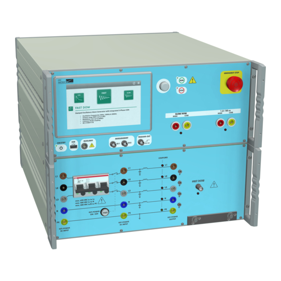
Not all accessories are used for all tests. The chapter “Perform a test” provides more informa- tion. 1.1 DOW3000 The DOW3000 generator is a compact system with all wave- forms for IEC 61000-4-18, IEC 61000-4-10 and several prod- uct standards. The Generator with an integrated 3-phase coupling and decoupling network is available in different ver-... -
Page 9: Cdn-Dow-Data-Hf (Pn 108321)
PARTNER 1 System Overview 1.3 CDN-DOW-DATA-HF (PN 108321) The CDN-DOW-DATA-HF is a compact coupling-decoupling network specifically designed to couple Slow DOW signals on 2-pair or 4-pair symmetrical high-speed communication lines. Both 1 MHz and 100 kHz signals can be coupled in common mode via 0.5 uF capacitors, according to IEC 60255-26. -
Page 10: Mf1000-1 (Pn 103480) And Mf1000-2 (Pn 103481)
PARTNER 1 System Overview 1.6 MF1000-1 (PN 103480) and MF1000-2 (PN 103481) Test coil for Slow DOW magnetic field test according IEC 61000-4-10. The MF1000-2 has more than twice the height of MF1000-1 for larger EUTs. 1.7 CN-EFT1000 (PN 103468) The clamp provides the ability of coupling the damped os- cillatory waves to the circuit under test without any galvanic connection to the terminals of the EUT’s ports, shielding of... -
Page 11: Veri50 Eft (Pn 103472)
PARTNER 1 System Overview 1.11 VERI50 EFT (PN 103472) 50 Ohm termination with SHV-BNC connector for the Fast DOW calibration together with a capacitive coupling clamp. Page 11/55... -
Page 12: Initial Operation
PARTNER 2 Initial Operation 2 Initial Operation 2.1 Unpacking and Checking 1. Check the packaging for signs of damage. If damage is visible, report this to the shipping company immediately. 2. Gently remove the equipment from the packaging. 3. Check the delivery for completeness using the delivery note and the accessory lists for the var- ious items. -
Page 13: Using The Generator
PARTNER 3 Using the Generator 3 Using the Generator 3.1 Front Panel 1 ON/STBY Power-up or power-down the generator. 2 Touchscreen Monitor User interface to perform all functions including test types selection, parameter entry, saving and recalling tests. 3 Rotary Knob Entry device enables faster navigation and parameter entry. - Page 14 8 Measurement Output BNC output for a direct connection to an oscilloscope to monitor the impulse of selected waveshape. In DOW3000, only CH1 is used for the 1.2/50 us insulation waveshape voltage measurement. See the technical data for more information.
-
Page 15: Rear Panel
PARTNER 3 Using the Generator 3.2 Rear Panel 1 AC Socket / Mains Fuse A country specific mains cable is delivered with the equipment, this should be used to connect to the mains power supply. A mains fuse is located in the socket housing. The value is indicated on the equipment type plate. -
Page 16: Software User Interface
PARTNER 3 Using the Generator • The green lamp indicates safety circuit open, no test can be started • The red lamp indicates safety circuit closed, tests can be started 3 RS485 Interfaces Interfaces to connect additional equipment that is controlled directly from the test equipment. 4 Ethernet Interface Remote control using TEMA3000 software via a common ethernet interface. - Page 17 PARTNER 3 Using the Generator Not all tests are available all the time. Availability depends on the hardware configuration. To simplify the menu structure, tests that are unavailable can be removed from the carousel. (General Menu) –> Settings –> Test Settings 2 Home button Select from any point in the menu structure to return to the main window.
-
Page 18: Perform A Test
PARTNER 4 Perform a Test 4 Perform a Test 4.1 Programming the Generator The same process is used to program the generator for different tests. In the first step, the parameters should be set according to the requirements of the test. 1 Main Category For quick access, categories at the bottom of the display contain groups of relevant parameters. -
Page 19: Run A Test
PARTNER 4 Perform a Test 4.2 Run a Test Starting a test by pressing the run button on the front panel, changes the display to the run view. 1 Information Area Indicates the most important information about a running test. 2 Progress Bar Indicates progress of the whole test and, if available, about the current cycle. -
Page 20: Slow And Fast Dow Test On Eut Power Ports
PARTNER 4 Perform a Test 4.3 Slow and Fast DOW Test on EUT Power Ports 1 Generator Select the desired waveform and frequency and CDN as coupling device. The same connection setup can be used for Slow DOW and Fast DOW. For Fast DOW, a reference ground plane must be used. -
Page 21: Slow Dow Magnetic Field Test
A missing coupling device in the parameter list can be added in the generator main menu. 2 Antenna The DOW3000 can be used either with the MF1000-1 or MF1000-2. Connect the antenna with a 2m MC-cable to the direct output of the generator. -
Page 22: Slow Dow Test On Unshielded And Unsymmetrical Interconnection Lines
PARTNER 4 Perform a Test 4.5 Slow DOW Test on Unshielded and Unsymmetrical Interconnection Lines 1 Generator Select the Slow DOW test and the CDN-DOW-DATA-LF as coupling device with the desired cou- pling type. A missing coupling device in the parameter list can be added in the generator main menu. 2 CDN-DOW-DATA-LF Connect the CDN with three 0.5 m MC-cables to the generator. -
Page 23: Slow Dow Test On Unshielded And Symmetrical Interconnection Lines
PARTNER 4 Perform a Test Common Mode Coupling of a single line to High and Low to PE. Coupling of multiple lines to PE is possible too. See the technical data for details. 4 EUT Connect the EUT to the output of the CDN. 5 Auxiliary Equipment Connect the auxiliary equipment (AE) to the input of the CDN. - Page 24 PARTNER 4 Perform a Test 2 CDN-DOW-DATA-HF Connect the CDN with three 0.5 m MC-cables to the generator. Two twisted cables for High and Low should be connected to the Slow DOW direct output; the third cable should be connected to the PE CDN output.
-
Page 25: Coupling Using Cdn-Dow-Data-Hf18 According To Iec 61000-4-18
PARTNER 4 Perform a Test 4.6.2 Coupling using CDN-DOW-DATA-HF18 according to IEC 61000-4-18 1 Generator Select the Slow DOW test and the CDN-DOW-DATA-HF18 as coupling device with the desired coupling type. A missing coupling device in the parameter list can be added in the generator main menu. 2 CDN-DOW-DATA-HF18 Connect the CDN with three 0.5 m MC-cables to the generator. - Page 26 PARTNER 4 Perform a Test You can select to couple either on 4 lines (2 pairs) or on 8 lines (4 pairs). Coupling on 4 lines can be selected by placing the MC-bridge L4, as well as the four MC-bridges J41-J44. Coupling on 8 lines can be selected by placing the MC-bridge L8, as well as the eight MC-bridges J81-J88.
-
Page 27: Fast Dow Capacitive Couplig Clamp
PARTNER 4 Perform a Test 4.7 Fast DOW capacitive couplig clamp 1 Generator All the equipment including generator and EUT must be placed on a ground reference plane. The generator earth bar on the frontpanel must be connected with the ground reference plane. Select the Fast DOW test and the CN-EFT1000 as coupling device. -
Page 28: Insulation 1.2/50
PARTNER 4 Perform a Test 4.8 Insulation 1.2/50 1 Generator Select the Insulation test. The correct output of the generator will be illuminated. 2 EUT The EUT must be unpowered during the insulation test. Otherwise the Generator can be damaged. 3 Measurement Equipment During the test, the voltage and current can be monitored with a current and voltage probe. -
Page 29: Slow Dow
PARTNER 4 Perform a Test 4.9.1 Slow DOW 1 Generator The calibration is carried out at the direct output of the generator. For a system calibration including the internal mains CDN or an external data line CDN, the calibration is carried out at the output of the CDN. -
Page 30: Fast Dow
PARTNER 4 Perform a Test 4.9.2 Fast DOW 1 Generator The calibration is carried out at the direct output of the generator. For a system calibration including the internal mains CDN, the calibration is carried out at the output of the CDN. For the calibration, an open and a short circuit measurement is required. -
Page 31: Fast Dow With Cn-Eft1000
PARTNER 4 Perform a Test 4.9.3 Fast DOW with CN-EFT1000 1 Generator Select the Fast DOW test and the CN-EFT1000 as coupling device. 2 CN-EFT1000 Connect the CN-EFT1000 with the Fast DOW direct output on the generator using a 2 m HV-BNC cable. -
Page 32: Slow Dow Magnetic Field
PARTNER 4 Perform a Test 4.9.4 Slow DOW Magnetic Field 1 Generator Select the Slow DOW test and the correct antenna as coupling device. The picture shows the setup with MF1000-1, the setup for MF1000-2 is similar. 2 Antenna Connect the MF1000-1 or MF1000-2 with the Slow DOW direct output on the generator using a 2 m twisted MC-cable. -
Page 33: Insulation
PARTNER 4 Perform a Test 4.9.5 Insulation 1 Generator The calibration is carried out at the direct output of the generator. For the calibration, an open and a short circuit measurement is required. 2 Measurement Equipment For calibration, an open and a short circuit measurement is required. •... -
Page 34: Additional Software Features
PARTNER 5 Additional Software Features 5 Additional Software Features 5.1 Protocols Select (General Menu) –> Protocols A protocol containing test parameters and results can be saved in the equipment. Additional information about the EUT and environment conditions can be added. 1 Last Protocol Shows a preview of the latest protocol, even if “Create Protocol”... -
Page 35: Store Setup
PARTNER 5 Additional Software Features The EMCP Library is read only. It is possible to copy a test from the library to the user space and edit the copy. 5.2.1 Store setup 1 Create New Setup Configure a test setup in a new window. The current test in the generator will not be changed. 2 Save Current Setup The currently configured test will be saved. -
Page 36: File Manager
PARTNER 5 Additional Software Features 2 Edit the Setup Click on a setup to edit, modify or delete from the list. Setups are stored as a copy in the setup linker. Any change to parameters does not affect the source file in the library. 3 Change Order Use the up and down arrows to move a setup position in the sequence. -
Page 37: Configuration
PARTNER 6 Configuration 6 Configuration 6.1 Settings Select (General Menu) –> Settings 1 Audio Volume and type of the different audio messages 2 Localisation Set equipment time and date and the required format. This information will be included in the test report and file data. -
Page 38: Generator
PARTNER 6 Configuration Risk of network errors Connection errors can affect the entire network. If the network does not support DHCP, or dynamic TCP/IP configuration is disabled, assign a valid address information before connecting the equipment to the LAN. Contact the local network administrator to obtain a valid IP address. -
Page 39: Remote Operation
• Easy to use test library with hundreds of tests • Seamless integration of your DSO Get in touch with your local representative or directly with EMC PARTNER for more information about TEMA3000. Go to www.emc-partner.com for a free software demo version. Page 39/55... -
Page 40: Maintenance And Service
Update via USB You can also download the newest version from www.emc-partner.com. Store the update file on a USB-Stick and transfer into the equipment via the USB port on the front panel. The update process starts automatically. -
Page 41: Customer Service
• Select (General Menu) –> Generator • In the tab Help select Copy to USB The information is transferred to the root folder of the USB. Send file by e-mail to service@emc-partner.ch 8.6 Recycling / Disposal RoHS directive 2011/65/EU The system complies with the directive 2011/65/EU (RoHS - Restriction of certain Hazardous Substances). -
Page 42: Technical Data
PARTNER 9 Technical Data 9 Technical Data 9.1 DOW3000 9.1.1 DOW Slow Standard IEC 61000-4-18:2019 ANSI C37.90 IEC 61000-4-12:1995 ENC50470-1 Open Circuit Frequency 100 kHz 10 % 1 MHz 10 % Level Direct Output 100 kHz 200 V - 5000 V... - Page 43 PARTNER 9 Technical Data Trigger Mode automatic manual external Coupling Device Direct Output Internal CDN The direct output must not be connected to powered pins. When a test on powered pins is necessary, proper coupling elements, e.g. 0.5 uF coupling capacitors, need to be used. Alternatively CDN outputs can be used since those are fit with coupling capacitors.
-
Page 44: Dow Fast
PARTNER 9 Technical Data 9.1.2 DOW Fast Standard IEC 61000-4-18:2019 Open Circuit direct and CDN output Level selectable 400 V - 4400 V calibrated 500 V - 4000 V 10 % Frequency 3 MHz 10 % 10 MHz 10 % 30 MHz 10 % Rise time... -
Page 45: Internal Cdn
PARTNER 9 Technical Data Coupling Device Direct Output Internal CDN CN-EFT1000 9.1.3 Internal CDN AC-Mode 50/60 Hz Voltage Line to Line max. 690 V AC Line to N max. 400 V AC Line to PE max. 400 V AC Current max. -
Page 46: Dow Slow Magnetic Field
PARTNER 9 Technical Data 9.1.4 DOW Slow Magnetic Field Standard IEC 61000-4-10:2016 Frequency 100 kHz 10 % 1 MHz 10 % Test Time 1 s to 65535 s Burst Repetition 100 ms to 200 s 10 % Burst Duration 1 ms to 20 s 10 % Pulse Spacing 100 kHz... -
Page 47: Insulation 0.5 Joule
PARTNER 9 Technical Data 9.1.5 Insulation 0.5 Joule Standard 61180-1/2 60060-1 62052-11 60255-27 60834-1/2 EN 50470-1 Open Circuit Level 500V +0 %/-10 % 1000V +0 %/-10 % 1500V +0 %/-10 % 2000V +0 %/-10 % 2500V +0 %/-10 % 3000V +0 %/-10 % 4000V +0 %/-10 % 5000V +0 %/-10 % 6000V +0 %/-10 %... -
Page 48: Dow3000 Main Generator
PARTNER 9 Technical Data 9.1.6 DOW3000 Main Generator Input Power Voltage 100 V - 240 V 10 % Frequency 50 Hz - 60 Hz Current max. 4 A Consumption Switched off 0 VA Standby <15 VA Test running max. 400 VA Dimensions 60 cm x 45 cm x 37 cm / 19"... -
Page 49: Mf1000-1
PARTNER 9 Technical Data 9.2 MF1000-1 Standard IEC 61000-4-8 IEC 61000-4-9 IEC 61000-4-10 Coil Size 1 m x 1 m Coil Factor 0.87 AC Magnetic field Range 1 0.8 A/m - 5.0 A/m continuous Range 2 5.0 A/m - 40 A/m continuous Range 3 40 A/m - 160 A/m... -
Page 50: Cdn-Dow-Data-Lf
PARTNER 9 Technical Data 9.4 CDN-DOW-DATA-LF Frequency 100 KHz 10 % 1 MHz 10 % Number of data lines up to 8 Coupling Differential Mode Differential on one pair Common Mode 1 Single Line to all other Lines (floating) Common Mode 2 Single Line to all other Lines (grounded over 0.5 µF) Common Mode Single Line to PE... -
Page 51: Cdn-Dow-Data-Hf
PARTNER 9 Technical Data 9.5 CDN-DOW-DATA-HF Standard IEC 61000-4-18:2019 IEC 60255-26:2013 Frequency 100 KHz 10 % 1 MHz 10 % Number of data lines 4 lines / 2 pairs (10/100 MBit/s) 8 lines / 4 pairs (1 GBit/s) Coupling Common Mode 1 One pair to all other pairs (floating) Common Mode 2 One pair to all other pairs (grounded over 0.5 µF) -
Page 52: Cdn-Dow-Data-Hf18
PARTNER 9 Technical Data 9.6 CDN-DOW-DATA-HF18 Standard IEC 61000-4-18:2019 Frequency 100 KHz 10 % 1 MHz 10 % Number of data lines 4 lines / 2 pairs (10/100 MBit/s) 8 lines / 4 pairs (1 GBit/s) Coupling Common Mode All pairs to PE Coupling capacitor 0.5 µF per line Open Circuit... -
Page 53: Adapter Box Rj45-8L
PARTNER 9 Technical Data 9.7 ADAPTER BOX RJ45-8L max. DOW Level 1500 V Dimension 22 cm x 7 cm x 3 cm Weigth 0.2 kg 9.8 VERI1K EFT Impedance 1000 Ω 2 % DC Ratio 50 ΩDSO Input 1:2000 1 MΩDSO Input 1:1000 Tolerance of Insertion Loss up to 100MHz... -
Page 54: Veri50 Eft
PARTNER 9 Technical Data 9.10 VERI50 EFT Impedance 50 Ω 2 % Ratio 50 ΩDSO Input 1:1000 1 MΩDSO Input 1:500 Tolerance of Insertion Loss up to 100MHz 0.5 dB up to 400MHz 3 dB Max. Level 7100 V EFT- or DOW-Impulse Max. -
Page 55: Veri-Cp-Eft
PARTNER 9 Technical Data 9.12 VERI-CP-EFT Standard IEC 61000-4-4 IEC 61000-4-18:2019 Dimension of the metallic part Width 120 mm 1 mm Length 1050 mm 1 mm Overall Dimension 113 cm x 7 cm x 5 cm Insulation EFT 5 ns / 50 ns 7.1 kV DOW 3 MHz / 10 MHz / 30 MHz 4.4 kV...
Need help?
Do you have a question about the DOW3000 and is the answer not in the manual?
Questions and answers