
Subscribe to Our Youtube Channel
Summary of Contents for Global A-Series
- Page 1 OWNER’S MANUAL M A730 Series 110-013-079 REV E ECO 202802 Date Effective: JUNE 2017...
- Page 2 IF OUTSIDE THE USA:1-636-861-3388 COPYRIGHT NOTICE © COPYRIGHT 2015, GLOBAL SURGICAL CORPORATION. NO PART OF THIS PUBLICATION MAY BE COPIED, PHOTOCOPIED, REPRODUCED, TRANSLATED, OR REDUCED TO ANY ELECTRONIC MEDIUM OR MACHINE-READABLE FORM, IN WHOLE OR IN PART, WITHOUT THE PRIOR WRITTEN CONSENT OF...
- Page 3 Congratulations on your purchase of the A-Series Surgical Operating Microscope System. We truly appreciate your business, and we’re grateful for the trust you’ve placed in us...
-
Page 4: Table Of Contents
Warnings and Cautions ......................1-2 Section 2 Unpacking Instructions ....................2-1 Section 3 Product Information ....................... 3-1 A-Series Surgical Operating Microscope Systems ............. 3-1 Microscope Support Systems Configurations ..............3-1 Section 4 Accessories ........................4-1 Microscope Components and Accessories ................. 4-1 Installation of Optical Accessories .................. - Page 5 Section 9 Technical Information ....................9-1 Microscope Support System Specifications................ 9-1 Binocular Focal Lengths......................9-1 M A801-LED Storage and Operations Specifications ............9-2 A-Series Microscope Total Magnification Chart ..............9-3 Finding Total Magnification ....................9-4 Effects of Changing Components ..................9-4...
-
Page 6: Section 1 Important Safety Instructions
Important Safety Instructions THE SAFETY AND SATISFACTION OF OUR CUSTOMERS AND THEIR PATIENTS WARNING ARE THE HIGHEST PRIORITIES OF GLOBAL SURGICAL CORPORATION. THIS MANUAL CONTAINS IMPORTANT INFORMATION REGARDING THE SAFE AND PROPER USE OF THIS EQUIPMENT AND SHOULD BE READ THOROUGHLY BY ALL OPERATORS PRIOR TO THEIR FIRST USE OF THE EQUIPMENT. -
Page 7: Warnings And Cautions
WHEN OPENING THE SHIPPING CARTON THE PLASTIC BANDS WILL SPRING APART WHEN CUT. ENSURE THEY WILL NOT HIT ANYONE OR ANYTHING. EYE WARNING PROTECTION SHOULD BE WORN WHEN REMOVING THE PLASTIC BANDS. WATCH FOR SHARP EDGES. CONTACT GLOBAL TECHNICAL SERVICES BEFORE REPLACING THE FUSE. WARNING... - Page 8 Using these solvents also presents a danger to individuals if the solvents are opened in a poorly ventilated room. Replacement parts, such as cables, must be purchased through Global Surgical to CAUTION ensure proper compliance requirements. The use of other cables may affect EMC performance.
- Page 9 Section 1 Important Safety Instructions This equipment needs special precautions regarding EMC and needs to be installed and put into service according to the EMC information provided in the installation CAUTION manual 110-013-080 M A730 Series Installation Manual. Portable and mobile RF communications equipment can affect medical electrical NOTICE equipment.
-
Page 10: Section 2 Unpacking Instructions
CAUTION When handling the optics do not touch the glass with your fingers. CAUTION Check for damage before discarding the shipping material and notify Global Surgical NOTICE Customer Service if shipping damage is observed. Contents are packed in several boxes. Before discarding any packaging ensure no NOTICE components are still within. -
Page 11: Section 3 Product Information
Microscope Support Systems Configurations The A-Series Microscope Support System is available in four configurations: Floor Stand Support System Model (M A730F) The floor stand support system model is designed for portability around the office/examination room. It uses a compact H-Base with four large casters, occupying minimal floor space. - Page 12 Section 3 Product Information Ceiling Mount Support System Model (M A730-C8, M A730-C9 and M A730C-10) The ceiling mount support system model is designed to permit maximum range of operation while eliminating the use of floor space. M A730C CEILING MOUNT M A730-C8 Ceiling Mount for a mounting height of 8 foot M A730-C9 Ceiling Mount for a mounting height of 9 foot M A730-C10 Ceiling Mount for a mounting height of 10 foot...
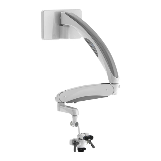
- Page 13 Section 3 Product Information Wall Mount Support System Model (M A730W) The wall mount support system model is designed for areas with limited floor space. It provides an unobstructed range of working area and folds flat against the wall for convenient storage.
-
Page 14: Section 4 Accessories
The A-Series M A1003 Microscope provides the user with 3 steps of magnification, the M A1004 provides 4 steps of magnification and the M A1006 Microscope provides 6 magnification steps. Each of the A-Series Microscopes may be used with a variety of A-Series binoculars, objective lenses and other accessories. - Page 15 Section 4 Accessories M A1047LFM Laser Filter This laser filter is meant for use with a corresponding specific wavelength laser and A-Series Microscope System equipped with a M A1047LFM laser filter module. M A1047LFM M 1047LFERB M 1047LFEC2 M 1047LFYG3...
- Page 16 Section 4 Accessories M A1061-SVA & M A1061-S50 Single Port Beamsplitter The single port beamsplitter models have one (1) mounting port for a camera adapter. The beamsplitter can be configured with a 50/50 prism M A1061-S50 or 95/5 prism M A1061-SVA. The M A1061-S50 model directs 50% of the light through the microscope toward a camera mounted on the side of the beamsplitter, while the other 50% of light passes through to the user’s eye.
- Page 17 Section 4 Accessories M A1021 Series Binoculars, The inclined binoculars are a more economical choice, but limited to a fixed 45 degree tilt angle. M A1020 Series Binoculars The straight binoculars are for use in ENT and otolaryngology and may also be used with the binocular co- observation systems.
- Page 18 5/8 inches tall for Aand G-Series binocular this is the ideal eyecup for users who do not wear glasses. M 1039G Low Profile Short Silicone Eyecup for A-Series Binocular Low profile 5/16 inches silicone eyecup for A-Series binocular. This is the ideal eyecup for users who wear glasses.
- Page 19 Section 4 Accessories Multiple Socket-Outlet ONLY CONNECT ITEMS THAT GLOBAL SURGICAL HAS SPECIFIED AS BEING WARNING COMPATIBLE WITH THE MICROSCOPE SYSTEM. CONNECTING EQUIPMENT THAT IS NOT INTENDED FOR USE WITH THE MICROSCOPE SYSTEM TO THE MULTIPLE SOCKET OUTLETS MAY RESULT IN INJURY AND/OR DAMAGE TO THE MICROSCOPE SYSTEM.
-
Page 20: Installation Of Optical Accessories
Port Virtual Beamsplitter, M A1017 Carr Adapter will install in very much the same way. See the installation instructions that are included with each accessory. Binocular Microscope Body Set Screw Microscope Body Objective Lens Figure 4-2 Installation of the A-Series M A1003, M A1004, and M A1006 Optics... -
Page 21: Installation Of The Multi Focal Objective Lens
The M A1028-200, M A1028-250 and M A1028-300 fine focus will install in very much the same NOTICE way. See the installation instructions that are included with each accessory. Microscope Body Lock Ring Shaft Multi-Focal Lens Knob Figure 4-3 Installation of the A-Series™ M A1028ML Multi-Focal Lens... -
Page 22: Section 5 Operating Instructions
Section 5 Operating Instructions Turning On The System THIS UNIT MUST BE USED ONLY WITH HOSPITAL GRADE EARTH-GROUNDED AC WARNING OUTLETS. Plug in the system into a hospital grade earth-ground AC outlet. Turn power on to the system by depressing the LED power button. -
Page 23: Counterbalancing Adjustment
Section 5 Operating Instructions It is best to set the feel of the microscope before attempting to use the microscope so the user comfort is optimized for the microscope procedures. Counterbalancing Adjustment Counterbalancing is done to ensure the microscope head moves with very little pressure (typically from user pressing on the eyecups) To do this the weight of the microscope head must be counterbalanced with the spring arm. -
Page 24: Pivot Adjustment
Section 5 Operating Instructions Pivot Adjustment Adjusts the amount of effort required to rotate the spring arm and extension arm from side to side. Push in the pivot knob until it pops out. Turn the pivot adjustment knob to the right to tighten the tension or turn to the left to loosen the tension. -
Page 25: Microscope Components
Figure 5-5 Microscope Components 5.11 Magnification Selection All A-Series M A1003, M A1004 and M A1006 Microscopes have two magnification factor selection knobs, one on each side of the microscope body. Either of these knobs should be turned until the desired magnification factor is facing the indicator arrow on the left side of the microscope body. -
Page 26: Focusing The Microscope
Section 5 Operating Instructions 5.12 Focusing The Microscope The coarse focus on the microscope system is achieved by raising or lowering the microscope assembly with the spring arm. Fine focus is obtained by moving the fine focus objective lens. The parfocal adjustment of the microscope allows the user to adjust the eyepieces to correct for nearsightedness or farsightedness. -
Page 27: M A801-Led Light Source Operation
Section 5 Operating Instructions 5.13 M A801-LED Light Source Operation nce the light source is installed, it is ready for operation. The light source has instant on/off capabilities. The power button will toggle power off and on with each press of the button. When power is first applied to the light source, the green bottom indicator light will turn on. -
Page 28: Brightness Settings And Memory
Section 5 Operating Instructions 5.14 Brightness Settings and Memory There are nine levels of brightness which can be selected using the buttons while the power is on. The level of brightness is indicated by the green indicator lights located on the keypad/control panel. An indicator light will light up for each increase in brightness See Figure 5-6. -
Page 29: Binocular Adjustment
5.17 Eyepieces The eyepieces used on A-Series Microscopes are high eye point eyepieces. This means that a full-sized image is formed approximately one inch (25 mm) above the eyepiece to assist users who wear glasses. Eyecups are used to position the user’s head at the correct distance from the eyepiece without the user becoming fatigued. -
Page 30: Fuse Replacement
IPD Wrong IPD Correct Figure 5-9 Diopter Adjustment 5.19 Fuse Replacement CONTACT GLOBAL TECHNICAL SUPPORT BEFORE REPLACING THE FUSE. WARNING DISCONNECT ALL ELECTRICAL POWER PRIOR TO REPLACING FUSE. WARNING USE ONLY A 5MM X 20MM CYLINDER, SLOW-BLOW, 6 AMP 250 VOLT FUSE. - Page 31 Section 5 Operating Instructions If your new fuse blows soon after installing it, you could have problems in that circuit. Contact NOTICE Global Surgical Technical Support for assistance. Remove 2 Screws Remove Cover and Remove Cover Open Fuse Compartment Replace with Two (2)
-
Page 32: Section 6 Care And Maintenance
Section 6 Care and Maintenance DISCONNECT ALL ELECTRICAL POWER PRIOR TO CLEANING AND DISINFECTING. WARNING RISK OF ELECTRIC SHOCK RESULTING IN DEATH OR INJURY IS POSSIBLE IF THE ELECTRICAL POWER IS NOT DISCONNECTED PRIOR TO CLEANING THE UNIT. Clean and disinfect after every patient according to CDC and OSHA requirements for NOTICE non-critical devices. -
Page 33: Section 7 Troubleshooting
Remove horizontal or 45 °arm cover, check to ensure that the LED power cord is securely plugged into one of the plugs on the multiple socket outlet located in the horizontal or 45° arm. For all other issues not Call Global Surgical Technical Services See Section 8.2 for contact covered above information. -
Page 34: Section 8 Service And Warranty
A return authorization is required before returning any product for warranty service by calling 1-800-861-3610. The customer is respon- sible for all shipping expenses. Global Surgical suggests using a method that will allow you to track the package in the event it does not arrive. -
Page 35: Technical Services Department
If service is required at your location, a skilled technician or sales representive will be dispatched within 24 hours. If you have questions that are not covered in this manual, please call the Global Surgical Technical Services Department as listed below:... -
Page 36: Section 9 Technical Information
Wall Surfaces: M 557 Note: Contractor to reinforce metal studded walls or particle walls. Standard Concrete (Cinder) Block 8” x 16” (203 mm x 406 mm) Table 9-2 A-Series Binocular Focal Lengths Binocular Model Focal Length M A1020 Series Straight Binocular 125 mm M A1021 Series 45°... - Page 37 Section 9 Technical Information Table 9-3 M A801-LED Storage and Operation Specifications ITEM SPECIFICATION Light Source Type Light Emitting Diode (LED) Color Temperature 5500°K LED Life 50,000 Hours (typical) Brightness Control Controls Light Output Range from 30%-100% Power Consumption 25 Watts Input Voltage 90-240 VAC, 50/60 Hz, 0.9A Output Voltage...
- Page 38 Section 9 Technical Information Table 9-4 A-Series Microscope Total Magnification Chart Turret Magnification Factor (X) 0.33 1.25 A-Series A3 Microscope A-Series A4 Microscope A-Series A6 Microscope 12.5 18.8 11.1 16.7 10.0 15.0 12.5 10.7 10.0 16.0 24.0 14.2 21.3 12.8 19.2...
-
Page 39: Binocular Focal Lengths
Table 9-2. Effects of Changing Components The following chart lists the effects of changing components to the microscope system. For further information, contact Global Surgical Technical Services Department. Table 9-5 Effects of Changing Microscope Components Field of... - Page 40 91613 Global Surgical Corporation 3610 Tree Court Industrial Blvd. St. Louis, MO 63122 EMERGO EUROPE Prinsessegracht 20 2514 AP The Hague The Netherlands...
Need help?
Do you have a question about the A-Series and is the answer not in the manual?
Questions and answers