Table of Contents
Advertisement
Quick Links
Tel +1 (717) 767-6511
Fax +1 (717) 764-0839
www.redlion.net
MODEL PAX2S – 1/8 DIN STRAIN GAGE INPUT PANEL METER
U L
C
US LISTED
R
3RSD
PROCESS CONTROL EQUIPMENT
DESCRIPTION
The PAX2S Strain Gage Panel Meter offers many features and performance
capabilities to suit a wide range of industrial applications. The PAX2S has a
strain gage input to handle various types of bridge configurations including load
cell, pressure and torque sensors. The optional plug-in output cards allow the
opportunity to configure the meter for present applications, while providing easy
upgrades for future needs.
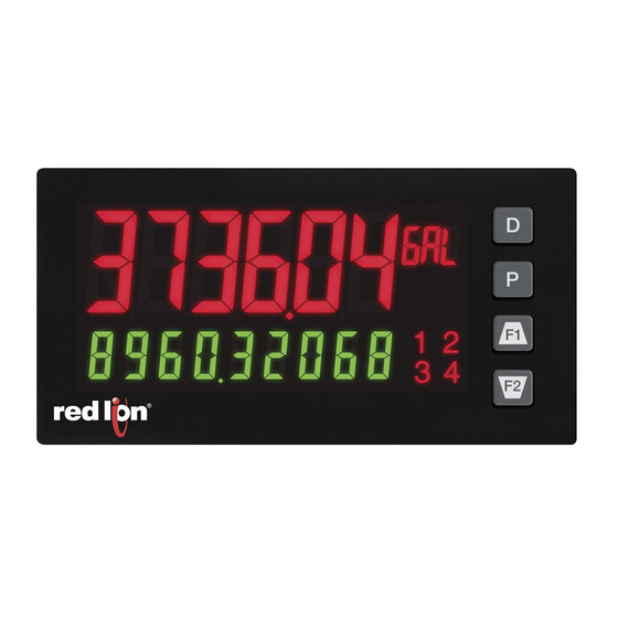
Highlighting the PAX2S is a dual line, display with a large 0.71", tri-color 6
digit top display line and a 0.35", 9 digit green bottom display line. The meter
also offers programmable units display, providing capability to tag the display
with units of measure. Display color change capability provides machine
operators a visual display of changing conditions, even when the operator is not
close enough to read the actual display value. In addition, a universal power
supply provides the ultimate in flexibility for both AC and DC power.
The meter provides a MAX and MIN reading memory with programmable
capture time. The capture time is used to prevent detection of false max or min
readings which may occur during start-up or unusual process events. The signal
totalizer (integrator) can be used to compute a time-input product. This can be
used to provide a readout of totalized weight or calculate service intervals of
motors, pumps, etc.
The meter has up to four setpoint outputs, implemented on plug-in option
cards. The plug-in cards provide dual FORM-C relays, quad FORM-A, or either
quad sinking or quad sourcing open collector logic outputs. The setpoint alarms
can be configured to suit a variety of control and alarm requirements.
The PAX2 can be programmed to utilize Modbus protocol. With Modbus, the
user has access to all configuration parameters. Readout values and setpoint
alarm values can be controlled through the bus. Additionally, the meter has a
feature that allows a remote computer to directly control the outputs of the
meter. Communication and bus capabilities are also available as option cards.
These include RS232, RS485, DeviceNet, and Profibus-DP.
DIMENSIONS In inches (mm)
1.95
(49.53)
3.80 (96.52)
Note: Recommended minimum clearance (behind the panel) for
mounting clip installation is 2.1" (53.4) H x 5.5" (140) W.
1
2
3
4
0.10
(2.54)
z LOAD CELL, PRESSURE AND TORQUE BRIDGE INPUTS
z UNIVERSAL AC/DC POWER SUPPLY
z SELECTABLE 5 VDC OR 10 VDC BRIDGE EXCITATION
z PROGRAMMABLE AUTO-ZERO TRACKING
z 6 / 9 DIGIT DUAL LINE/TRI-COLOR DISPLAY WITH 0.71" & 0.35"
DIGITS
z PROGRAMMABLE UNITS DISPLAY
z VARIABLE CONTRAST AND INTENSITY DISPLAY
z UP TO 160 SAMPLES PER SECOND CONVERSION RATE
z BUILT-IN USB PROGRAMMING PORT ENABLING UNIT
CONFIGURATION WITH CRIMSON PROGRAMMING SOFTWARE
z NEMA 4X/IP65 SEALED FRONT BEZEL
The PAX2 includes a built-in USB programming port. With a Windows
based program, made available by Red Lion Controls, configuration data can be
downloaded to the PAX2 without the need of any additional option cards.
A linear DC output signal is available as an optional plug-in card. The card
provides either 20 mA or 10 V signals. The output can be scaled independent of
the input range and can track either the input, totalizer, max or min readings, or
any setpoint value.
After the meter has been initially configured, the parameter programming
may be locked out from further modification in its entirety, or allowing selected
values accessible for quick entry.
The meter has been specifically designed for harsh industrial environments.
With NEMA 4X/IP65 sealed bezel and extensive testing of noise effects with
regard to CE requirements, the meter provides a tough reliable application
solution.
SAFETY SUMMARY
All safety related regulations, local codes and instructions that appear in this
literature or on equipment must be observed to ensure personal safety and to
prevent damage to either the instrument or equipment connected to it. If
equipment is used in a manner not specified by the manufacturer, the protection
provided by the equipment may be impaired. Do not use this unit to directly
command motors, valves, or other actuators not equipped with safeguards. To do
so can be potentially harmful to persons or equipment in the event of a fault to
the unit.
CAUTION: Risk of Danger.
Read complete instructions prior to
installation and operation of the unit.
1.75
(44.45)
4.14 (105)
1
Bulletin No. PAX2S-B
Drawing No. LP0885
Released 04/13
®
CAUTION: Risk of electric shock.
PANEL CUT-OUT
3.60 (91.44)
Advertisement
Table of Contents

Related Manuals for red lion PAX2S

Summary of Contents for red lion PAX2S
- Page 1 After the meter has been initially configured, the parameter programming Highlighting the PAX2S is a dual line, display with a large 0.71", tri-color 6 may be locked out from further modification in its entirety, or allowing selected digit top display line and a 0.35", 9 digit green bottom display line.
-
Page 2: Table Of Contents
General Meter Specifications ... . . 3 Programming the PAX2S ....9 Optional Plug-In Output Cards ... . 4 PAX2S Modbus Register Table . -
Page 3: General Meter Specifications
eneral eTer peCifiCaTiOns 1. DISPLAY: Positive image LCD 12. CUSTOM LINEARIZATION: Top Line - 6 digit, 0.71" (18 mm), with tri-color backlight (red, green or Data Point Pairs: Selectable from 2 to 16 orange), display range: -199,999 to 999,999; Display Range: -199,999 to 999,999 Bottom Line - 9 digit, 0.35"... -
Page 4: Optional Plug-In Output Cards
These plug-in cards include: Adding Option Cards The PAX2S meters can be fitted with up to three optional plug-in cards. The PAXCDS10 - Dual Relay, FORM-C, Normally open & closed details for each plug-in card can be reviewed in the specification section below. -
Page 5: Installing The Meter
(Torque to approximately 7 in-lbs [79N-cm]). Do not over-tighten the screws. The PAX2S meets NEMA 4X/IP65 requirements when properly installed. The unit is intended to be mounted into an enclosed panel. Prepare the panel cutout to the dimensions shown. -
Page 6: Installing Plug-In Cards
These cards plug into the main circuit board of the meter. The 1. With the meter removed from the case, locate the plug-in card connector for plug-in cards have many unique functions when used with the PAX2S. the card type to be installed. The types are keyed by position with different main circuit board connector locations. - Page 7 4.1 POWER WIRING AC Power DC Power AC/DC AC/DC AC/DC AC/DC AC/DC AC/DC The power supplied to the meter shall employ a 15 Amp UL approved circuit breaker for AC input and a 1 Amp, 250 V UL approved fuse for DC input. It shall be easily accessible and marked as a disconnecting device to the installed unit.
-
Page 8: Front Panel Keys And Display Overview
Display Parameters programming section for configuration details. line 2 display lOOps Main Display Loop The PAX2S offers three display loops to allow users quick access to needed information. In the Main display loop, the D key is pressed to sequence through the selected Line 2 values. -
Page 9: Programming The Pax2S
6.0 p paX2s rOgramming It is recommended that program settings be recorded as programming is performed. A blank Parameter Value Chart is provided at the end of this bulletin. PROGRAMMING MODE ENTRY In Programming Menu: The Programming Mode is entered by pressing the P key. Full... - Page 10 (INPUt) npuT arameTers INPUT SELECT INPUt ANALOG USEr ANALOG Select the Input to be programmed. ANALOG INPUT PARAMETERS ( ANALOG This section details the programming for the analog input. INPUt rANgE rAtE dECPNt round tArE FILtEr bANd POINtS StYLE INPUt dISPLY INPUt ANALOG...
- Page 11 SCALING STYLE INPUT VALUE FOR SCALING POINT 2 INPUt key-in data -199999 999999 StYLE apply signal APPLY 0. 0 0 For Key-in (KEY), enter the known second Input Value by using the ! or @ If Input Values and corresponding Display Values are known, the Key-in arrow keys.
- Page 12 PROGRAMMING MODE LOCK-OUT STORE BATCH READING IN TOTALIZER USEr-n USEr-n Programming Mode is locked-out, as long as activated (maintained action). A security code can be configured to PLOC allow programming access during lock-out. The Input Display value is added (batched) to the Totalizer when activated (momentary action) and the display flashes bAtCh.
- Page 13 RESET MINIMUM DISPLAY SELECT PARAMETER LIST USEr-n USEr-n r-LO r-LO LISt LISt When activated (momentary action), rESEt flashes and the Minimum resets Two lists of values are available to allow the user to either switch between to the present Input Display value. The Minimum function then continues from two sets of setpoints, or setpoints and scaling parameters and/or Line 1 &...
- Page 14 SETPOINT OUTPUT PARAMETERS (SEtPNt) This section details the programming for the setpoints. To have output capabilities, a setpoint Plug-in card needs to be installed into the PAX2S (see Ordering Information). Depending on the card installed, there will be two or four setpoint outputs available. If no output card is installed, programming for the setpoints is still available.
- Page 15 Setpoint Alarm Figures With reverse output logic , the below alarm states are opposite. SP + ½Hys SP + Hys SP + (-Dev) SP - ½Hys ALARM ALARM ALARM STATE STATE STATE TRIGGER POINTS TRIGGER POINTS TRIGGER POINTS Absolute Low Acting (Unbalanced Hys) = Deviation High Acting (Dev <...
- Page 16 SETPOINT ANNUNCIATOR LINE 1 CHANGE COLOR Annun Color FLASH NO CHG GrEEN OrANGE NO CHG GrnOrG rEdOrG rEdGrn LINE 1 The nor mode displays the corresponding setpoint annunciators of “on” This parameter allows the Line 1 Display to change color, or alternate alarm outputs.
- Page 17 (dISPLY) isplay arameTers DISPLAY SELECT dISPLY LINE 1 LINE 2 SCNdrY tOtAL LINE 1 Select the Display to be programmed. LINE 1 PARAMETERS (LINE 1) This section details programming for the Line 1 (Top Line) Display. The Input, Gross, Tare, Total, Maximum (HI) and Minimum (LO) capture values and setpoints can be shown on the Line 1 display.
- Page 18 LINE 2 PARAMETERS (LINE 2) This section details programming for the Line 2 (Bottom Line) Display. The Input, Gross, Tare, Total, Max, Min, Setpoint, Band/Deviation values and Parameter List A/B status can be shown on the Line 2 display. The display loops described below are used to view, reset and modify the selected display values, based on the Line 2 Value Access setting programmed for each available value.
- Page 19 The characters available for the programmable modes include: SELECTION DESCRIPTION Reset Setpoint output 2 A b C d E F G H I J k L M N O P q r S t U W Y Z 0 1 Reset Setpoint output 3 - = [ ] / °...
- Page 20 SECONDARY FUNCTION PARAMETERS (SCNdrY) dISPLY HI-ASN HI-t LO-ASN LO-t dSP-t At-t At-bnd dISPLY SCNdrY 1 . 0 1 . 0 0 . 0 2 MAX Capture MAX Capture MIN Capture MIN Capture Display Auto-Zero Auto-Zero Assignment Time Assignment Time Update Rate Tracking Time Tracking Band MAX (HI) CAPTURE ASSIGNMENT...
- Page 21 -days (/86400) hour Example: A PAX2S is monitoring the total weight of material on a 20 ft This is the time base used in Totalizer accumulations. If the Totalizer is being conveyor. The conveyor operates at a constant rate of 1 ft/sec. The Totalizer accumulated through a user input programmed for Batch, then this parameter will calculate the total weight of material output from the conveyor.
- Page 22 Following a Modbus command or RLC Transmit Value command, the PAX2S will wait this minimum amount of time in seconds before issuing a serial Select either 7 or 8 bit data word lengths. Set the word length to match the response other serial communications equipment on the serial link.
- Page 23 The PAX2S supports serial communications using the optional serial communication cards or via the USB programming port located on the side of the unit. When USB is being used (connected), the serial communication card is disabled. When using the standard RS232 and RS485 Pax option cards, the PAX2S supports both the RLC protocol and also supports Modbus communications.
-
Page 24: Pax2S Modbus Register Table
Values less than 65,535 will be in (LO word). Values greater than 65,535 will continue into (Hi word). Negative values are represented by two’s complement of the combined (Hi word) and (LO word). Note 1: The PAX2S should not be powered down while parameters are being changed. Doing so may corrupt the non-volatile memory resulting in checksum errors. REGISTER... - Page 25 SERIAL RLC PROTOCOL COMMUNICATIONS Register Identification Chart RLC Communications requires the Serial Communications Type Parameter VALUE DESCRIPTION MNEMONIC APPLICABLE COMMANDS/COMMENTS (tYPE) be set to “rLC”. Input (relative T, P, R (Reset command resets input value) to zero; tares) SENDING SERIAL COMMANDS AND DATA TO THE METER Total T, P, R (Reset command resets total When sending commands to the meter, a string containing at least one...
- Page 26 RECEIVING DATA FROM THE METER Analog Output Register (AOR) ID: W Data is transmitted by the meter in response to either a transmit command (T), This register stores the present signal value of the analog output. The range a print block command (P) or User Function print request. The response from of values of this register is 0 to 4095, which corresponds to the analog output the meter is either a full field transmission or an abbreviated transmission.
- Page 27 COMMAND RESPONSE TIME Timing Diagrams The meter can only receive data or transmit data at any one time (half-duplex operation). When sending commands and data to the meter, a delay must be NO REPLY FROM METER imposed before sending another command. This allows enough time for the meter to process the command and prepare for the next command.
-
Page 28: Factory Service Operations
METER CALIBRATION connected and ready. Using the chart below, step through the five selections to be calibrated. At each prompt, use the PAX2S ! and @ keys to adjust the COdE output so that the external meter display matches the selection being calibrated. -
Page 29: Troubleshooting Guide
TROUBLESHOOTING PROBLEM REMEDIES No Display At Power-Up Check power level and power connections No Display After Power-Up Check Display Module: , and program settings. d-LEU d-Cont LINE 1 Program Locked-Out Check for Active User Input, programmed for . Deactivate User Input. PLOC Enter proper access code at prompt. -
Page 30: Parameter Value Chart
PARAMETER VALUE CHART Programmer ________________ Date ________ PAX2S Meter# _____________ Security Code ________ INPUt INPUT SETUP PARAMETERS DISPLAY PARAMETER USER SETTING Analog Input Parameters DISPLAY 9 VALUE ANALOG dISPLY 9 INPUT 10 SCALING VALUE INPUt 10 DISPLAY PARAMETER USER SETTING... - Page 31 DISPLAY PARAMETER USER SETTING Line 1 Display Scroll Enable/Time ScroLL LIST B CUSTOM MNEMONICS Line 1 Units Mnemonic(s) UNItS LABEL MNEMONIC LABEL Input List A List B Gross Line 1 Units Digit 1 (Left) Unit 1 Tare Line 1 Units Digit 2 (Center) Unit 2 Total Line 1 Units Digit 3 (Right)
- Page 32 This page intentionally left blank.
- Page 33 This page intentionally left blank.
- Page 36 The Company disclaims all liability for any affirmation, promise or representation with respect to the products. The customer agrees to hold Red Lion Controls harmless from, defend, and indemnify RLC against damages, claims, and expenses arising out of subsequent sales of RLC products or products...
Need help?
Do you have a question about the PAX2S and is the answer not in the manual?
Questions and answers