Table of Contents
Advertisement
Quick Links
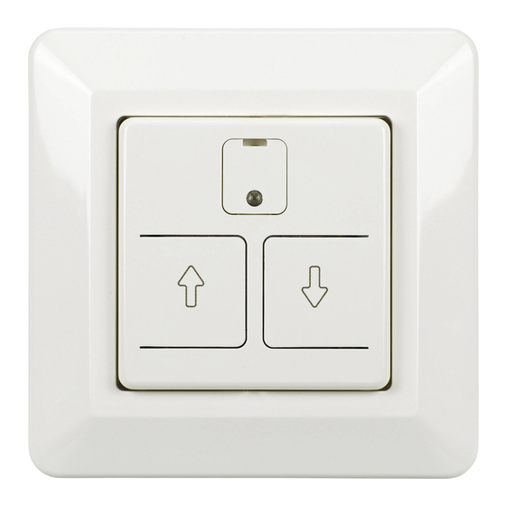
Installation and operating manual
ELECTRONIC SWITCH FOR SUN BLINDS
for flush-mounting
The switches for sun blinds are manufactured in accordance
with the latest technological facts and are subject to
continuous quality controls.
Please read the installation and operating manual carefully
to avoid mistakes and ensure proper functioning.
General description:
The microprocessor controlled sun blind switch can be used to control motor-driven roller blinds
and sun blinds with limit switches (230V / 50Hz motors).
The manual up / down / stop function is activated by simply touching the keys.
By pushing the up / down keys for 3 seconds, an up and a down motion time can be
programmed which is repeated in a 24 hour cycle.
Due to the 50 x 50mm central plate in accordance with DIN 49075, it can be integrated into
almost all common switch programs with the respective intermediate frames.
very simple programming
no clock needs to be set
24 hours automatic function
programming lock
emergency power backup in the
simple formation of groups possible
case of power failure
External inputs: Extension unit operation, formation of groups
All kinds of 230V signal transmitters, such as push buttons, time switches, photoelectric lighting
controllers, wind sensors etc. can be connected to the inputs "Extern " and "Extern ". It is
essential to always connect the same L-conductor which is connected to the blind
switch.
It is possible to combine several blind switches to one group by simply connecting the external
inputs in parallel. These groups can then also be controlled centrally via push buttons, time
switches or a blind switch as well (Fig. 2 and 4). As signals which are present for a longer
period of time are also evaluated as a short impulse, no other functions are blocked. For this
reason, it is possible to connect even customary signal transmitters with extended signal
duration (e.g. time switches, shortest switching time usually 1 min.) to these inputs.
Technical data:
Mains voltage:
230V~, +6/-10%, 50Hz
Switching capacity:
max. 750VA
max. motion time:
180s
In the case of a power failure, the performed programming will be saved for max. 60 minutes.
The device, however, must have been in operation for at least 20 minutes while the mains
voltage was available.
Installation and safety instructions:
The blind switch can be installed into all customary flush boxes with Ø 60mm and can be
used with 50x50mm central plates in accordance with DIN 49075.
Per blind switch, only one motor may be connected (refer to the motor manufacturer's
instructions). If more than one motor is connected to the blind switch, use appropriate cut-off
relays.
Always the same phase which is connected to the contact "L" must be connected to the
inputs "Extern
" and "Extern
". The maximum wire length at these inputs should not
exceed 100m.
Requested function:
1. Move blind "Up"
or "Down"
2. Stop moving blind
3. Perform programming
Activate automatic function
4. Change a programmed time
5. Temporarily deactivate the automatic function
(the programmed
(up) /
(down) times will be
saved)
6. Lock device against unauthorized programming
change
7. Permanently delete programmed
/
(automatic function is deactivated)
8. Check if the automatic function is activated
Operation of the blind switch:
key (up) or (down)
input "Extern " or "Extern "
setting screw "lock / delete programming"
At a push of the respective key, the motion time is triggered and the
blind moves to its stop position (stop depends on the setting of the
motor's limit switches).
The maximum motion time is 180 seconds. Then, the drives are de-
energized.
Switch signal to the respective input.
Shortly actuate any key,
Apply signal to the opposite input.
At the desired time of day, push e.g. the key
LED blinks (at least 3 seconds).
(Perform the same with key
The programming cannot be carried out via the external inputs.
The easiest way to change a programmed time is to overwrite it. To
do so, follow the steps in point 3.
Push the keys
pushed for at least 3 seconds until the red LED blinks.
(By pushing them again for 3 seconds, the automatic function can
be restarted.)
Permanently turn the setting screw from position "0" to position
"lock".
Shortly turn the setting screw from position "0" to position "delete".
times
Then, turn it back to position "0".
Shortly actuate the key
Please make sure that there are no persons or objects in the motion range of the blinds.
Regarding electronic tubular motors, refer to the manufacturer's instructions concerning the
programming line.
Works at the 230V mains supply must only be carried out by a specialist
under consideration of the valid regulations (e.g. DIN-VDE).
All works must only be carried out when the mains voltage is switched off.
If the device is opened or tampered with, the warranty will expire.
Assembly
1. Switch off the power
supply and secure it
against being switched
on.
2. Connect the device
according to the
connection diagrams
(stripping length of wires
8mm).
3. Use mounting claws or
screws to fix the device
in the flush box.
4. Screw on cover frame,
intermediate frame and
central plate.
5. Attach lens.
6. Switch on power.
Help in case of malfunctions:
Error occurred:
The blinds move into the wrong
direction when the keys and
are actuated
When the blinds are operated via
the external inputs, they move into
the wrong direction
The blind does not move
If disturbances from the mains (e.g. switching processes) affect the function of the device
temporarily, a motion which is possibly being carried out is stopped. Afterwards, regular
operation is again possible.
What to do:
or
(up) until the red
(down) at the desired time of day).
(up) and
(down) simultaneously and keep them
or
Cover frame
Installation
device
Red LED
The accompanying different-sized pegs can be used to compensate differences
in height due to plaster or wallpapers (wallpaper compensation) or the
differences in height caused by the use of different switch programs.
Possible causes / measures:
motor connectors wrong, swap the connectors at the
outputs "Motor " and "Motor "
Swap the connectors at the inputs "Extern " and
"Extern "
Due to a previous operation, the blind motor has
become too hot (the thermal protection of the motor
has triggered) – wait for a couple of minutes
No mains voltage available – check fuse
The blind motor is defective - replace
The blind switch is defective - replace
Explanation:
If an automatic function has been programmed beforehand, the
red LED will glow for 5 seconds when the blind is moved. Manual
commands at the arrow keys
and
the automatic function and signals at the inputs "Extern
"Extern
".
This means that a blind moving in this direction
stopped by a signal at "Extern
"
When the key is actuated, the blind starts to move and the LED
glows. As soon as the LED starts to blink, the key can be
released. Now, the movement in the direction which has just been
carried out is saved for this time of day.
The blind will now move into the respective direction every day at
the programmed time.
The previous automatic time is replaced by the newly
programmed time.
When the keys are pushed simultaneously, the red LED glows.
When it has recognized the command, the LED blinks for 5
seconds. The temporary deactivation of the automatic function
always applies to both directions of movement.
Now, the device cannot be programmed. An existent automatic
function will still be carried out.
If the automatic function is programmed and activated, the red
LED glows for 5 seconds when the blind is moved. (The automatic
function may also be deactivated temporarily, see 5.)
Intermediate frame for
inserts 50 x 50 mm
Central plate
Mounting screw
Lens
always have priority over
" or
can only be
Rev.05/06 19.19.154.07 GB.doc
Advertisement
Table of Contents

Summary of Contents for ehmann 6660C0026
- Page 1 Please make sure that there are no persons or objects in the motion range of the blinds. Installation and operating manual Regarding electronic tubular motors, refer to the manufacturer’s instructions concerning the ELECTRONIC SWITCH FOR SUN BLINDS programming line. for flush-mounting Works at the 230V mains supply must only be carried out by a specialist under consideration of the valid regulations (e.g.
- Page 2 With blind switch 1, a group of further devices in any amount can be controlled centrally Fig. 2: Fig. 1: Individual (manually or with program). Blind switches 2 and 3 control individually on the spot (manually or with program). control of a sun blind lock delete lock...
Need help?
Do you have a question about the 6660C0026 and is the answer not in the manual?
Questions and answers