Table of Contents
Advertisement
Quick Links
Advertisement
Table of Contents

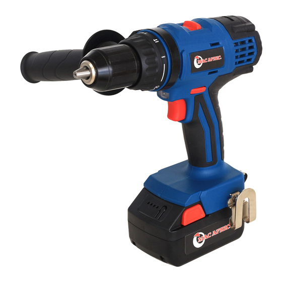
Summary of Contents for ADENDORFF MAC AFRIC SDRILC-005
-
Page 2: General Power Tool Safety Warnings
GENERAL POWER TOOL SAFETY WARNINGS 9. If operating a power in a damp location is unavoidable, use a residual current device (For All Power Tools) (RCD) protected supply. Use of an RCD reduces the risk of electric shock. WARNING! Read and understand all instructions. Failure to follow all NOTE: The term “residual current device (RCD)”... -
Page 3: Specifications
controlled with the switch is dangerous and must be repaired. Service 19. Disconnect the plug from the power source and/or the battery from the power tool 28. Have your power tool serviced by a qualified repair person using only identical Such This will ensure that the safety of the power tool is maintained. -
Page 4: Additional Safety Rules
bit insert can jam and lead to loss of control over the tool. ADDITIONAL SAFETY RULES 11. Keep hands away from rotating parts. 1. To be safe, disabled, retarded, untrained people or people disable to operate 12. Always be sure to have a firm footing and be sure no one is below when using the tool in independently, including young children, are discouraged to operate the tool without high locations. -
Page 5: General Descriptions
repair is required; incorrect reassembly may result in a risk of electric shock or fire. 20. Do not charge for the battery when room temperature is lower than 10℃ or higher than 50℃. The battery cannot be charged when room temperature is lower than 0℃. 8. -
Page 6: Instructions For Operation
INSTRUCTIONS FOR OPERATION battery indicator when pressing the battery button or switching on the tool. (Fig. 4) Installing or Removing the Battery Four red LED lights are set to indicate the CAUTION: battery power which can be referred to the ... - Page 7 Icons of Charging Descriptions of Indicator Lights Descriptions of Icons Charging Indicator FFCL18-01 SCHARG-001 SCHARG-001 Charging Status Model Green Lights FFCL18-03 FFCL18-04 (FFCL18-05) Light Light Input Voltage (AC) 220-240V 110-240V 220-240 Plug the charger into Green light flickers, red Charging Current 3.0A 2.0A a proper outlet...
-
Page 8: Speed Change
2. Removing instrument Counterclockwise Rotation To remove the bit, hold the ring and turn the Depress the reversing switch lever from side A sleeve counterclockwise (view backwards). to side B for counterclockwise rotation for loosening or unscrewing screws. (Fig 9) (Fig. -
Page 9: Work Light
Work Light and shorten the service life of the tool. The white LED work light will be lit after There is a tremendous force exerted on the tool/bit at the time of break- through. Hold pulling the switch trigger for illumination of the tool firmly and exert care when the bit begins to break through the work piece. -
Page 10: Overload Protection
Tightening Bolt Removing Bolt CAUTION: To remove the bolt, hammer the point of the driver bit at the bolt head and force the tool 1. Set the tap position at the low speed. properly. Switch on the tool slowly and then Nominal Diameter Recommended Size speed it up gradually. -
Page 11: Maintenance And Inspection
a) Remove the battery from the tool when it is worn out. ※ To maintain product SAFETY and RELIABILITY, repairs, any other maintenance or adjustment should be performed by authorized service centers, always using original b) Wrap the terminals with a strong tape to avoid short-circuit and electric leakage. replacement parts. - Page 12 EXPLANATION OF GENERAL VIEW Screw PCB Board Drill Chuck SG13D1/2 Terminal Block Assembly Mechanical Transmission Battery Cartridge Combination Speed Controller Battery Charger Gear Ball Bearing 695ZZ/R-1350ZZ Armature Assembly Ball Bearing 625ZZ Stator Assembly Brush Holder Assembly Spring (Left) Spring (Right) Carbon Brush Rear Cover Pan Head Tapping Screw ST2.9×20...
- Page 13 EXPLANATION OF GENERAL VIEW (Mechanical Transmission Combination) Gear Housing Cover Inner Gear A Washer (17×43.5×0.5) Planet Gear A Rear Gear Housing Planet Carrier A Steel Ballφ5 Stopper Plate Washer (23×41×0.5) Washer Front Gear Housing Spring Click Spring Plate Roundwire Snap Ring 9 Dial Plate Ball Bearing 699ZZ Washer (33×46×3.6)...
Need help?
Do you have a question about the MAC AFRIC SDRILC-005 and is the answer not in the manual?
Questions and answers