Table of Contents
Advertisement
Quick Links
Pacific Antenna Easy TR Switch Kit
Kit Description
The Easy TR Switch is an RF sensing circuit with a double pole double throw relay that can be used to automatically
switch an antenna between a separate receiver and transmitter.
It also has a second switched pair of inputs and outputs that can be used for other switching applications such as
muting or switching an audio channel or even to switch a remote amplifier or pre-amplifier.
Manual operation is achieved through use of control inputs to disable RF switching and to key the relay.
Features and Specifications
Provides automated or manual switching
Two independent sets of inputs and outputs
Automatic Rf sensing requiring as little as 50mW of RF for switching
Frequency range of 160-6M
Power handling of up to 125 Watts
All on a 2 by 2 inch circuit board.
Support
PACIFIC ANTENNA
QRP KITS.COM
qrpkits.com@gmail.com
Easy TR Switch V3 20171212
1
Advertisement
Table of Contents

Subscribe to Our Youtube Channel
Related Manuals for Pacific Antenna Easy TR

Summary of Contents for Pacific Antenna Easy TR
- Page 1 Pacific Antenna Easy TR Switch Kit Kit Description The Easy TR Switch is an RF sensing circuit with a double pole double throw relay that can be used to automatically switch an antenna between a separate receiver and transmitter. It also has a second switched pair of inputs and outputs that can be used for other switching applications such as muting or switching an audio channel or even to switch a remote amplifier or pre-amplifier.
- Page 2 □ DO NOT use a large soldering iron or soldering gun. □ If you are a beginner, new to soldering, there are a number of resources on the web to help you get on the right track soldering like a pro. Google Soldering Techniques. Easy TR Switch V3 20171212...
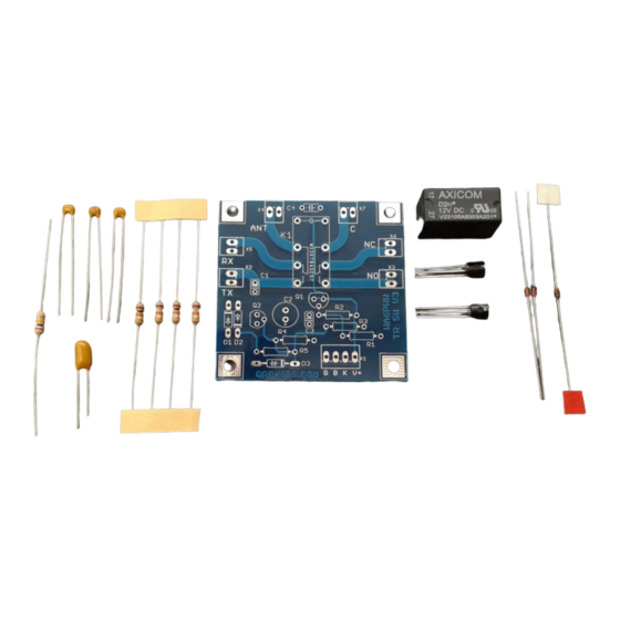
- Page 3 2N3906 PNP Transistor BS170 N-Channel MosFet Relay Axicom V23105 12V relay Circuit Board labeled TR SW V3 Typical Parts Appearance Note: Some parts may vary in appearance from those shown here due to source changes. Easy TR Switch V3 20171212...
- Page 4 1N5240 (align band to board outline), Note: confirm labels on diodes with magnifier Misc parts Axicom V23105 Relay, (only fits one way due to pin configuration) Header Pin header that can be used for connection if wires are not to be directly soldered Easy TR Switch V3 20171212...
- Page 5 In general, increase C1 for lower frequency and/or lower power operation and decrease it for high frequency and or high power use. Board Connections Aux. Antenna Normally Closed Normally Open The Antenna, RX and TX as well as the second switched pair (C, NC and NO) are as shown above. Easy TR Switch V3 20171212...
- Page 6 The additional switched contacts (if used), are connected in the same manner. Connect Connect center of center of BNC here BNC here Connect center of Connect center of BNC here BNC here Easy TR Switch V3 20171212...
- Page 7 Pin 4: Ground for power, control and key signals Troubleshooting The Easy TR switch is intended to be easy to assemble and should operate without any problems. However, if it fails to operate, there are a few things to check: Check the board for cold solder joints, these will appear rough rather than shiny.
- Page 8 Schematic Easy TR Switch V3 20171212...
Need help?
Do you have a question about the Easy TR and is the answer not in the manual?
Questions and answers