Table of Contents
Advertisement
Quick Links
Thank you for purchasing a Sealey product. Manufactured to a high standard this product will, if used according to these instructions and properly maintained,
give you years of trouble free performance.
IMPORTANT: PLEASE READ THESE INSTRUCTIONS CAREFULLY. NOTE THE SAFE OPERATIONAL REQUIREMENTS, WARNINGS & CAUTIONS. USE THE PRODUCT
CORRECTLY AND WITH CARE FOR THE PURPOSE FOR WHICH IT IS INTENDED. FAILURE TO DO SO MAY CAUSE DAMAGE AND/OR PERSONAL INJURY AND WILL
INVALIDATE THE WARRANTY. PLEASE KEEP THESE INSTRUCTIONS SAFE FOR FUTURE USE.
1.
SAFETY INSTRUCTIONS
1.1.
PERSONAL PRECAUTIONS
3 When using this multimeter, please observe all normal safety rules concerning:
Protection against the dangers of electrical current.
Protection of the meter against misuse.
3 Full compliance with safety standards can only be guaranteed if used with the test leads supplied. If necessary, they must be replaced with genuine Sealey
leads with the same electronic ratings. Failure to do so will invalidate the warranty.
7 DO NOT use leads if damaged or if the wire is bared in any way.
1.2.
GENERAL SAFETY INSTRUCTIONS
3 Familiarise yourself with the application and limitations of the multimeter as well as the potential hazards. IF IN ANY DOUBT CONSULT A QUALIFIED ELECTRICIAN.
3 When the meter is connected to a circuit, do not touch unused meter terminals.
3 When the value to be measured is unknown beforehand, set the range selector to the highest value.
3 Before rotating the range selector to change functions, disconnect test leads from the circuit under test.
p WARNING! Never perform resistance measurements on live circuits.
3 Always be careful when working with voltages above 60Vdc or 30Vac rms. Keep your fingers behind the probe barriers while measuring.
3 Before attempting to insert transistors for testing, ensure that test leads have been disconnected.
3 Components should not be connected to the transistor socket, capacitor socket or temperature socket when taking voltage measurements with the test leads.
3 When not in use, store the multimeter carefully in a safe, dry, childproof location. Storage temperature range -10
2.
FEATURES
High quality general purpose multimeter with a large (25mm), clear and easy to read LCD display. Supplied with full set of leads and probes.
Measures:
Function
• AC and DC Volts
V
• DC Amps
V~
• Ohms Resistance
A
10A
• Diode/Transistor
hFE
Verification Mode
Ω
3.
OPERATION
WARNING! Ensure that you read, understand and apply the safety and operational instructions before connecting the multimeter. Only when you are sure
p
that you understand the procedures outlined, is it safe to proceed with testing.
Operating temperature range 0
Remember to turn on multimeter before use and to turn it off when measurement is completed.
NOTE: WHEN THE FIGURE ‘1’ IS DISPLAYED, IT INDICATES AN OVER-RANGE SITUATION AND A HIGHER RANGE NEEDS TO BE SELECTED.
3.1.
MEASURING VOLTAGE
3.1.1.
Connect the black test lead to the ‘COM’ input socket and the red test lead to the ‘VΩmA’ input socket.
3.1.2.
Set the rotary switch to the required ‘V
of the red test lead connection will be indicated when measuring dc voltages.
3.2.
MEASURING CURRENT
3.2.1.
Connect the black test lead to the ‘COM’ input socket and the red test lead to the ‘VΩmA’ input socket for measuring a maximum of 200mA.
For a maximum of 10A connect the red lead to the 10A
3.2.2.
Set the rotary switch to the required ‘A
red lead connection will be indicated when measuring dc.
3.3.
MEASURING RESISTANCE
3.3.1.
Connect the black lead to the ‘COM’ input socket and the red test lead to the the ‘VΩmA’ input socket (the polarity of the red lead is ‘+’).
3.3.2.
Set the rotary switch to the required ‘Ω’ range and connect the test leads across the resistance under measurement.
3.3.3.
When checking in-circuit resistance, ensure that the circuit under test has all power removed and all capacitors have been fully discharged.
3.3.4.
When measuring resistance over 1MΩ, the meter may take a few seconds to get a stable reading. This is normal for high resistance measurements.
3.4.
DIODE TESTING
3.4.1.
Connect the black lead to the ‘COM’ input socket and the red lead to to the ‘VΩmA’ input socket (the polarity of the red lead is ‘+’).
3.4.2.
Set the rotary switch to the ‘
will show the approximate forward voltage of the diode. If the leads are reverse connected, only ‘1’ is displayed.
Red Lead Connection
Input Limits
VΩmA
1000v.c. dc
VΩmA
750v.c. ac (sine)
VΩmA
200mA dc
10ADC
10A dc
N/A
N/A
VΩmA
N/A
VΩmA
N/A
C to 40
C.
O
O
‘ (dc) or ‘V ~ ‘ (ac) range and connect test leads across the source or load under measurement. The polarity
socket.
‘ (dc) range and connect test leads in series with the load under measurement. The polarity of the
‘ position and connect the red lead to the anode and the black lead to the cathode of the diode under test. The meter
INSTRUCTIONS FOR:
19 FUNCTION DIGITAL
MULTIMETER
MM19.V2
MODEL:
C to 50
C.
O
O
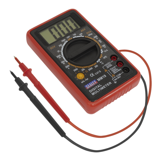
Layout:
1. LCD Display.
2. Rotary Switch.
3. Input Sockets.
4. Transistor Socket
4
1
2
3
MM19.V2 - 1 - 201204
Advertisement
Table of Contents

Related Manuals for Sealey Professional MM19.V2


Summary of Contents for Sealey Professional MM19.V2
- Page 1 Protection of the meter against misuse. 3 Full compliance with safety standards can only be guaranteed if used with the test leads supplied. If necessary, they must be replaced with genuine Sealey leads with the same electronic ratings. Failure to do so will invalidate the warranty.
- Page 2 93/68/EEC CE Marking Directive For Jack Sealey Ltd. Sole UK importer of Sealey Professional Tools. NOTE: It is our policy to continually improve products and as such we reserve the right to alter data, specifications and component parts without prior notice.
Need help?
Do you have a question about the Professional MM19.V2 and is the answer not in the manual?
Questions and answers