Table of Contents
Advertisement
Advertisement
Table of Contents

Summary of Contents for Physik Instrumente E-509 Series
- Page 1 Artisan Technology Group is your source for quality new and certified-used/pre-owned equipment SERVICE CENTER REPAIRS WE BUY USED EQUIPMENT • FAST SHIPPING AND DELIVERY Experienced engineers and technicians on staff Sell your excess, underutilized, and idle used equipment at our full-service, in-house repair center We also offer credit for buy-backs and trade-ins •...
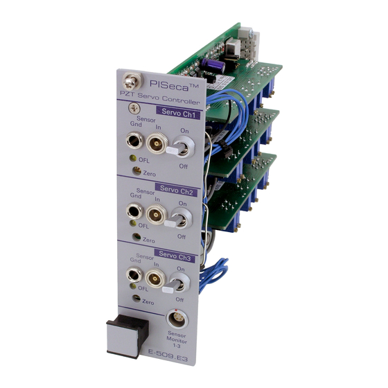
- Page 2 PISeca™ Capacitive Sensors E -509.E03 Signal Conditioner for Single-Plate PISeca™ Capacitive Sensors © Physik Instrumente (PI) GmbH & Co. KG Auf der Römerstr. 1 ⋅ 76228 Karlsruhe, Germany Tel. +49-721-4846-0 ⋅ Fax: +49-721-4846-299 info@pi.ws ⋅ www.pi.ws Artisan Technology Group - Quality Instrumentation ... Guaranteed | (888) 88-SOURCE | www.artisantg.com...
- Page 3 Artisan Technology Group - Quality Instrumentation ... Guaranteed | (888) 88-SOURCE | www.artisantg.com...
- Page 4 Physik Instrumente (PI) GmbH & Co. KG is the owner of the following company names and trademarks: PI®, PIC®, PICMA®, PILine®, PIFOC®, PiezoWalk®, NEXACT®, NEXLINE®, NanoCube®, NanoAutomation® Copyright 1999–2009 by Physik Instrumente (PI) GmbH & Co. KG, Karlsruhe, Germany. The text, photographs and drawings in this manual enjoy copyright protection. With regard thereto, Physik Instrumente (PI) GmbH &...
- Page 5 P osition Servo-Control Module are described in their own manuals. All documents are available as PDF files from w ww.pi.ws or by email from your Physik Instrumente Sales Engineer or i nfo@pi.ws H T U U T H Artisan Technology Group - Quality Instrumentation ... Guaranteed | (888) 88-SOURCE | www.artisantg.com...
-
Page 6: Table Of Contents
E-509 Position Servo-Control Module User Manual PZ 77E Contents Introduction ..............6 1.1. Safety Precautions ..............6 1.2. Prescribed Use ................7 1.3. Model Survey ................7 1.4. Front Panels................. 9 Quick Start..............9 E-509 Design.............. 11 3.1. Signal Path Diagram ..............12 3.2. -
Page 7: Introduction
E-509 Position Servo-Control Module User Manual PZ 77E 1. Introduction E-509 is a displacement-sensor and position-servo-control module for PZT actuators. The module is used in the E-500-series electronics and allows controlling the position (displacement) of piezoelectric devices with nanometer resolution. It can also be installed in E-470, E-471, E-480 and E-481 high-voltage amplifier systems, giving them servo-control capability. -
Page 8: Prescribed Use
E-509 Position Servo-Control Module User Manual PZ 77E 1.2. Prescribed Use Based on their design and realization, E -509 modules are intended to be used installed in compatible housings, like the PI E-500/E-501 series chassis. They must not be used for applications not in conformance with this manual. Observe the safety precautions given in this User Manual. - Page 9 E-509 Position Servo-Control Module User Manual PZ 77E 1.3.1. Submodules (pre-installed on the E-509 T P F FP T E-801.1x Sensor-processing submodule for SGS sensors (present on E- 509.Sx/E-509.S3S) E-801.2x Sensor-processing submodule for LVDT sensors (present on E-509.Lx) E-802.5x Position Servo-Control submodule (present on all except E-509.E03) The submodules are described in separate manuals: E-801 submodules in PZ117E, E-802.55s in PZ150E, and all former E-802.5x versions in PZ113E.
-
Page 10: Front Panels
E-509 Position Servo-Control Module User Manual PZ 77E 1.4. Front Panels PZT-SERVO CONTROLLER SERVO SENSOR MONITOR ZERO SENSOR E-509 Fig. 2: LVDT and SGS versions Fig. 3: Typical front panels of the different share the same front panels capacitive sensor versions* *The predecessors of E-509.CxA models were E-509.Cx;... - Page 11 E-509 Position Servo-Control Module User Manual PZ 77E 3. Connect the PZT voltage supply cables to the power amplifier module (in the same chassis, near the E-509). Again, in multi-axis systems, make sure the proper PZTs are connected to the proper channels. CAUTION—High Voltage The piezo amplifiers used with this product are high-voltage devices capable of generating high output currents.
-
Page 12: E-509 Design
E-509 Position Servo-Control Module User Manual PZ 77E Connect the included E-808.90 sensor monitor cable to the Sensor Monitor 1- 3 socket. The sensor monitor signal shows the current position of the sensor probe in relation to the target and the selected measurement range. See Section 4 .3.3 for details on how to adjust target surface and probe... -
Page 13: Signal Path Diagram
E-509 Position Servo-Control Module User Manual PZ 77E 3.1. Signal Path Diagram Fig. 4: Signal path (only one channel shown) in a system with an E-509 Servo- Controller, a PZT power amplifier and an E-516 Computer Interface and Display Module. Note that "Control In" and "DC-offset" on the amplifier module do not control the amplifier directly, but only determine “Control Out”... -
Page 14: Submodules
E-509 Position Servo-Control Module User Manual PZ 77E 3.2. Submodules Some functions of the E-509 are implemented on plug-in submodules , as T P F FP T discussed in the following sections. It should not be necessary to remove or replace the submodules, but if you ever do so, be sure to face the component sides as illustrated, ( F ig. -
Page 15: Sensor Processing And Servo-Control Functions
E-509 Position Servo-Control Module User Manual PZ 77E 3.3. Sensor Processing and Servo-Control Functions The E-509 modules normally come pre-installed in an appropriate PI chassis (except for OEM versions). The system is calibrated at the factory with the associated PZT actuators. If, however, you should need to recalibrate your system, see Section and the E- 802 Servo-Control Submodule User Manual. -
Page 16: E-509 Calibration Routines
E-509 Position Servo-Control Module User Manual PZ 77E 4. E-509 Calibration Routines For most applications, only the zero point has to be realigned from time to time to compensate for temperature changes. Further adjustments are not required and not recommended as long as system components are not exchanged or modified. NOTE All basic calibration adjustments are done in PI lab before shipment. - Page 17 E-509 Position Servo-Control Module User Manual PZ 77E Static gain (sensor range) adjustment: Static PZT displacement calibration requires an external expansion gauge with appropriate resolution (e.g. 0.01 µm for a P-841.30 actuator) and a precision voltmeter. The accuracy of calibration depends on the resolution of the external measurement system.
- Page 18 E-509 Position Servo-Control Module User Manual PZ 77E 11 Again using the ZERO potentiometer, adjust the PZT output voltage as follows: For HV amplifiers: set voltage to approx. -50 V For LV amplifiers: set voltage to approx -5 V The zero-point setting is now close enough to allow checking of the PZT output range 12 Check the PZT output range by applying a voltage which goes from 0 V to +10 V to the CONTROL INPUT and watching the voltage at PZT socket in parallel...
- Page 19 E-509 Position Servo-Control Module User Manual PZ 77E Scan the voltage at CONTROL INPUT from 0 V to +10 V and read the PZT displacement using an external gauge. Adjust the Integrated Linearization System (ILS) by turning the ILS potentiometer (see F ig.
-
Page 20: Dynamic Calibration
E-509 Position Servo-Control Module User Manual PZ 77E Scan the voltage at CONTROL INPUT from 0 V to +10 V and read the PZT displacement using the external gauge. With +10 V the external gauge should show the PZT at about nominal expansion. Adjust with the sensor gain trim potentiometer ( F ig. - Page 21 E-509 Position Servo-Control Module User Manual PZ 77E If not ordered otherwise, the following settings are used for calibration (see p. for different settings and location of the adjustment elements): Bandwidth 3 kHz Sensor output voltage 0 to 10 V range Measurement range Standard extension range factor of...
- Page 22 E-509 Position Servo-Control Module User Manual PZ 77E 4.3.2. Sensor Monitor Signal For each sensor channel, the sensor monitor signal available on the E-509.Ex front panel indicates the gap size between target surface and sensor probe, known as the probe-to-target gap. The sensor monitor signal can be used to adjust target and probe (see Section 4 .3.3 below for how to proceed).
-
Page 23: Disposal
EU mixed with other wastes. To meet the manufacturer’s product responsibility with regard to this product, Physik Instrumente (PI) GmbH & Co. KG will ensure environmentally correct disposal of old PI equipment that was first put into circulation after 13 August 2005, free of charge. -
Page 24: E-509 Technical Data
E-509 Position Servo-Control Module User Manual PZ 77E 6. E-509 Technical Data E-509.C1A / E-509.C2A / E-509.L1 / E-509.S1 / E-509.C3A E-509 L3 E-509.S3 E-509.E3 E-509.E03 Function Sensor Sensor Sensor Sensor Sensor electronics and electronics and electronics and electronics and electronics only, position servo- position servo-... - Page 25 E-509 Position Servo-Control Module User Manual PZ 77E E-509.C1A / E-509.C2A / E-509.L1 / E-509.S1 / E-509.C3A E-509 L3 E-509.S3 E-509.E3 E-509.E03 Sensor connector LEMO LEMO LEMO LEMO LEMO EPL.00.250.NTD ERA.0S.304.CLL ERA.0S.304.CLL ECP.00.650.NLL ECP.00.650.NLL see note see note .543 Triax .543 Triax X 1 1 X T P F...
-
Page 26: Two-Plate Cap. Sensor On-Board Sensor Processing
E-509 Position Servo-Control Module User Manual PZ 77E 6.1. Two-Plate Cap. Sensor on-board Sensor Processing The E-509.CxA versions have the sensor processing on the main board. The adjustment elements affecting sensor processing which are described in this section are for use only if the controller/actuator configuration is changed or elements are replaced. - Page 27 E-509 Position Servo-Control Module User Manual PZ 77E 6.1.2. Jumpers and On-Board Switch Code Selection for measurement range, see table below: JPx01–JPx06: Default setting: 1.0 factor of extention 0.56 0.68 0.75 1.25 2.13 of measurement range measurement JPx06 JPx05 Jumper JPx04 Position JPx03...
-
Page 28: Single-Plate Cap Sensor On-Board Sensor Processing
E-509 Position Servo-Control Module User Manual PZ 77E Jumper Settings for Master and Slave On systems with multiple E-509s or another timing source, the excitation frequencies are synchronized by the appropriate use of jumpers for master and slave. JP1 and JP2 both set to same side: left=Master, right=Slave Default setting: SLAVE Fig. - Page 29 E-509 Position Servo-Control Module User Manual PZ 77E Fig. 11: E-509.E3 and E-509.E03 layout (“x” in jumper designations stands for channel number: 1,2 or 3) 6.2.1. Adjustment Potentiometers: Note: Numbering of some jumpers and potentiometers is channel-specific: “x” can be 1, 2 or 3 depending on the channel number TRx01: Sensor gain TRx02:...
- Page 30 E-509 Position Servo-Control Module User Manual PZ 77E 6.2.2. Jumpers and on-board Switch JP101, JP110 and JP111: Measurement Range Extension Factor Together these jumpers determine the factor applied to the measurement range. Supported are settings for 1 (default), 2, 2.5 and 5 times the standard range of the sensor head used.
-
Page 31: Pin Assignments
E-509 Position Servo-Control Module User Manual PZ 77E 7. Pin Assignments 7.1. 32-Pin Main Connector, DIN 41612 7.1.1. LVDT and SGS 3-Channel (E-509.S3, E-509.L3) Pin No. Function Pin No. Function internal use OUT: ch1 (control) IN: +15 V IN: +15 V IN: -15 V IN: -15 V Sync LVDT+**... -
Page 32: Sensor-Monitor Output
E-509 Position Servo-Control Module User Manual PZ 77E 7.1.3. Capacitive Sensor Versions (E-509.C1A, E-509.C2A, E-509.C3A, E-509.E3, E-509.E03) Function on Function on Pin No. Pin No. .C3A, .Ex** .C2A .C1A .C3A, Ex** .C2A .C1A n.c. Control signal output CH1 + 15 V + 15 V - 15 V - 15 V... - Page 33 E-509 Position Servo-Control Module User Manual PZ 77E 7.2.2. Three-channel SGS- and LVDT-sensor versions (E-509.S3, E-509.L3): The SENSOR MONITOR socket (LEMO) on the front panel also carries the signals from all three channels. Each (E-509.S3, E-509.L3, E-509.S3S) comes with the E-808.90 Sensor-Monitor cable. The purpose of this cable is simply to split up the SENSOR MONITOR output signal (LEMO) for the three Fig.
-
Page 34: Sensor Connections
E-509 Position Servo-Control Module User Manual PZ 77E 7.3. Sensor Connections 7.3.1. Connection of Strain Gauge Sensors For more details or when replacing actuators, see the E-801 Sensor Submodule User Manual. Fig. 14: Strain gauge sensor wiring for various actuators Release 2.8.4 www.pi.ws Page 33... - Page 35 E-509 Position Servo-Control Module User Manual PZ 77E 7.3.2. Connection of LVDT Sensors Sensors working on the principle of LVDTs usually have a coil with a primary winding, two secondary windings and a moving core. If an AC current is applied to the primary winding, it produces a magnetic field which is concentrated by the soft iron or ferrite core.
- Page 36 E-509 Position Servo-Control Module User Manual PZ 77E 7.3.3. Connection of 2-Plate Capacitive Sensors The sensor probe and target plates form a air-capacitor. Its capacitance value, depending on the separation of the both plates, is compared with an internal reference capacitor of C = 10 pF.
-
Page 37: Appendix-Single-Plate Piseca™ Capacitive Sensors36
E-509 Position Servo-Control Module User Manual PZ 77E 7.3.4. Connection of Single-Plate PISeca™ Capacitive Sensors The E-509.E3 and E-509.E03 have the triaxial sockets required to connect with PISeca™ single-plate capacitive sensors. The sensor cable carries the sensor signal surrounded by an active shield, all inside a grounded shield. The conductive reference plane is electrically connected to the unit on a separate cable via a banana jack. -
Page 38: Measurement Range
E-509 Position Servo-Control Module User Manual PZ 77E 8.2. Measurement Range The measurement range depends on the size of the active sensor area as well as on the electronics used. Fig. 19: Definitions: measurement range and mid-range distance have identical values Due to PI’s proprietary signal conditioner electronics design, the mid-range distance is always identical to the selected measurement range. -
Page 39: Target Plane
E-509 Position Servo-Control Module User Manual PZ 77E Linearity is influenced to a high degree by the homogeneity of the electric field and thus by any non-parallelism of the probe and target in the application. PI capacitive position sensor electronics incorporate a proprietary design providing superior linearity, low sensitivity to cable capacitance, low background noise and low drift. - Page 40 E-509 Position Servo-Control Module User Manual PZ 77E Measurement range extension factor: set by jumpers JPx10, JPx11 and JPx01 on the E-509.Ex module (see p. ) ; if multiplied by the nominal measurement range gives the extended measurement range Gap: distance between sensor probe surface and target surface. In the calibrated range the minimum probe-to-target gap equals 50% and the maximum gap 150% of the measurement range value Target area / target surface: denotes the surface against which the measurement...
- Page 41 Artisan Technology Group is your source for quality new and certified-used/pre-owned equipment SERVICE CENTER REPAIRS WE BUY USED EQUIPMENT • FAST SHIPPING AND DELIVERY Experienced engineers and technicians on staff Sell your excess, underutilized, and idle used equipment at our full-service, in-house repair center We also offer credit for buy-backs and trade-ins •...
Need help?
Do you have a question about the E-509 Series and is the answer not in the manual?
Questions and answers