
Related Manuals for Kuhnke 610.441.31

Summary of Contents for Kuhnke 610.441.31
- Page 1 Kuhnke Electronics Instruction Manual Ventura Smart Solution Power Heat Controller E 774 GB 30.06.2014 / xxxxxx...
- Page 2 This technical information is primarily directed to system designers, project engineers and device develop- ers. It does not contain any availability information. All specifications are only of a descriptive nature and are not to be understood as warranted properties in a legal sense. Exact properties and characteristics shall be agreed in the specific contract. Claims for damages against us - on whatever grounds - are excluded, except in instances of deliberate in- tent or gross negligence on our part.
-
Page 3: Table Of Contents
KUHNKE Automation Table of Contents Table of Contents 1 Modification History ............................6 2 Introduction ..............................8 3 Reliability, Safety ............................. 9 Intended Use ............................9 Target Group ............................9 Reliability .............................. 9 Symbols ............................... 9 3.4.1 Danger .............................. 10 3.4.2 Attention ............................ - Page 4 Table of Contents KUHNKE Automation 6.5.3 Requirements for the output lines ....................30 Mounting Lid ............................30 7 Thermo-controller Operation ......................... 31 Starting up ............................31 Indicators ............................31 7.2.1 Status Indicators..........................31 Status Signalling by Thermo-controller ....................33 7.3.1 Module State ............................ 33 7.3.2 Channel State...........................
- Page 5 KUHNKE Automation Table of Contents E 774 GB 30.06.2014...
-
Page 6: Modification History
Introduction 1 Modification History Version Date Subject E774D 31/08/2010 Initial release based on the tailored power heat controller model E774D 09/12/2010 Addenda to the installation and change of fuse sections Details about the PROFIBUS fieldbus interface E774D 12/05/2011 New / changed functions at migration from software release SW 2.01 to SW 2.02 or SW 1.04 of hardware HW 1.0x 7.5.1 Channel Error at Pilot Stage 7.5.3... - Page 7 KUHNKE Automation Introduction Version Date Subject Correction of the phase assignment at the output terminals E774 06.08.2013 Extension of the manual with UL requirements E774 03.03.2014 Extension Accessories, Fuse Adapter E774 24.04.2014 5.3 Auxiliary Supply "24VDC", X10 (extension "fuse according UL 248) E774 19.05.2014...
-
Page 8: Introduction
Introduction 2 Introduction General functionality The 9-channel thermo-controller is a power controller with the ability to actu- ate ohmic consumers. Ohmic consumers are normally contact heaters or in- frared radiators (IR radiators). The thermo-controller needs less space in the switching cabinet than solid state relays and is a cheaper alternative to the classic PLC-based control, specifically when it comes to detecting failing consumers. -
Page 9: Reliability, Safety
3.3 Reliability Reliability of Kuhnke products is brought to the highest possible standards by extensive and cost-effective means in their design and manufacture. These include: •... -
Page 10: Danger
Reliability, Safety KUHNKE Automation 3.4.1 Danger This symbol warns you of dangers which may cause death or grievous bodily harm if operators fail to implement the precautions described. 3.4.2 Attention This symbol draws your attention to information you must take a look at to avoid malfunctions, possible material damage or dangerous states. -
Page 11: Project Planning And Installation
This applies to section 8 (Ad- missible deviations when working on parts) in particular. • Repairs must be carried out by specially trained Kuhnke staff only (usually in the main factory in Malente). Warranty expires in every other case. -
Page 12: Electromagnetic Compatibility
Reliability, Safety KUHNKE Automation 3.6 Electromagnetic Compatibility 3.6.1 Definition Electromagnetic compatibility is the ability of a device to function satisfacto- rily in its electromagnetic environment without itself causing any electromag- netic interference that would be intolerable to other devices in this environ- ment. -
Page 13: Electrical Immission Safeguard
KUHNKE Automation Reliability, Safety 3.6.4 Electrical Immission Safeguard To bleed electromagnetic interference, connect the controller to operative earth and ensure best-practice wiring. Susceptibility to noise Electromagnetic Compatibility (EMC) - Part 6-2: Generic standards - Immu- nity for industrial environments (IEC 61000-6-2:2005);... - Page 14 Reliability, Safety KUHNKE Automation E 774 GB 30.06.2014...
-
Page 15: System Description
KUHNKE Automation 4 System Description 4.1 Overview Description of functionality The 9-channel thermo-controller is a power controller with the ability to actu- ate ohmic consumers. Ohmic consumers are normally contact heaters or IR radiators. Load voltages can be fed through a bus bar. Separate fuses are thus un- necessary which minimises the amount of space and time needed for instal- lation. -
Page 16: Ventura Thermo-Controller Hardware Design
System Description KUHNKE Automation 4.2 Ventura Thermo-controller Hardware Design Block diagram E 774 GB 30.06.2014... -
Page 17: Technical Properties
KUHNKE Automation 4.3 Technical Properties VENTURA Smart Solution 9-channel thermo-controller Power controller Load current 9 x 4000 W (each channel carrying max. 10A) Load type resistive Mains voltage 3 x 400 VAC (±10%) without N wire For Europe: 3 x 400 V AC (± 10%) without N conductor, to the TT, TN-C or TN... -
Page 18: Pin Wiring
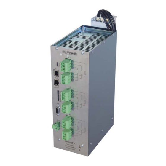
System Description KUHNKE Automation 5 Pin Wiring 5.1 Power Heat Controller on EtherCAT® All plug-type ports are lo- cated at the front panel of the thermo-controller. 5.1.1 Connectors Device status LED EtherCAT IN Terminals, channels 1..3 EtherCAT OUT Terminals, channels 4..6... -
Page 19: Auxiliary Supply "24Vdc", X10
KUHNKE Automation 5.2 Auxiliary Supply "24VDC", X10 The thermo-controller features an on-board power supply unit designed for an input voltage of 24 VDC (18V ... 32V). The power supply unit is internally protected against polarity reversal and limits the inrush current. It supplies power to the thermo-controller's circuitry and is required to measure the mains voltage. -
Page 20: Device With Ethercat® Fieldbus Port, X7, X8
KUHNKE Automation 5.3 Device with EtherCAT® Fieldbus Port, X7, X8 5.3.1 EtherCAT® Fieldbus Port X7, X8 Connector X7/X8/ wiring: X7/X8 Function RJ45 75 Ohm 75 Ohm 75 Ohm 75 Ohm 5.3.2 Device and EtherCAT® Status 5.3.2.1 "EtherCAT®" LED (RUN/ERROR) The LED labelled "EtherCAT®" indicates the state of the EtherCAT® ASIC. -
Page 21: Output Channel Terminals, X1
KUHNKE Automation 5.4 Output Channel Terminals, X1 … X6 Connector 3-pin, male, up to 6 mm , Connector included in package Use male connector SPC 5/ 3-ST-7.62 (1996029) Max. lead length to consumer location: 30m The operation of the Power Heat Controller without connectors X1 ... -
Page 22: Operative Earth / Protective Earth
KUHNKE Automation 5.5 Operative Earth / Protective Earth Connect operative earth/protective earth to the protective earth conductor of the switching cabinet or the system that the thermo-controller is installed in. Connection is made to the bolt on top of the device. -
Page 23: Mounting - Installation - Start-Up
KUHNKE Automation 6 Mounting - Installation - Start-up 6.1 General Technically skilled handling of the equipment and compliance with the appli- cable regulations are prime requirements for reliably excluding all dangers for humans and property when working with electric energy. -
Page 24: Preparatory Steps
KUHNKE Automation 6.2.2 Preparatory Steps Attention: To avoid accidents, disconnect unit from the mains prior to installing or ser- vicing it. Install the units in a suitable housing and protect them against dirt. Only qualified persons to set up and service the unit! -
Page 25: Installation Using The Mounting Rail Adapter
KUHNKE Automation 6.2.3 Installation Using the Mounting Rail Adapter The rail adapter attaches the thermo-controller to 60 mm bus bar systems, and the combination foot fits onto 5 mm and 10 mm thick double-T or triple-T bus bars between 12 mm and 30 mm wide. -
Page 26: Removing From The Rail Adapter
KUHNKE Automation To mount the unit onto the rail • Prior to mounting the adapter, verify that the blue rail lock has snapped out. • Place the unit on the rail and push it down until you here it go click. -
Page 27: Power Supply
KUHNKE Automation 6.3 Power Supply Power is supplied through the mounting rail adapter. The power supply must meet the following criteria: For Europe: 3 x 400 V AC (± 10%) without N conductor, to the TT, TN-C or TN Network identification / network configurations in the USA... -
Page 28: Protective Earth Conductor
KUHNKE Automation 6.4 Protective Earth Conductor The thermo-controller is designed for installation in a switching cabinet whose IP 20 housing provides sufficient protection against direct contact. Attach a protective earth conductor to provide for protection against indirect contact in case of a fault to frame. Connection is made to the 4 mm bolt on the top or on the bottom of the device. -
Page 29: Output
KUHNKE Automation 6.5 Output 6.5.1 Branch Circuit protection according UL 508A UL 508A specifies how output wires for use are to be protected. Compliance with the following points is mandatory. • Every PHC output wire shall be protected (UL 508 31.2.1) because it is energized towards the ground potential. -
Page 30: Requirements For The Output Lines
KUHNKE Automation 6.5.3 Requirements for the output lines The output lines must meet the general requirements. particular, however, note: • The maximum cable length between the consumer and the heater manufacturer shall not exceed 30 m. Interpretation of the output lines to UL 508A •... -
Page 31: Thermo-Controller Operation
KUHNKE Automation 7 Thermo-controller Operation Do not plug, mount, unplug or touch the connectors during operation! You may otherwise provoke destruction or malfunction. Turn off all power sources before working on the modules. This also applies to any peripherals connected such as encoders, programming devices with external power source, etc. - Page 32 KUHNKE Automation The LED next to "CPU Error" outputs various flash codes to indicate errors in the thermo-controller power drive, 'flash code' meaning a number of flash pulses within an interval followed by a pause, in this case. If an error is limited to one or several heating channels, only the LEDs of the affected channels will flash the same code.
-
Page 33: Status Signalling By Thermo-Controller
KUHNKE Automation 7.3 Status Signalling by Thermo-controller 7.3.1 Module State The thermo-controller continuously returns the "Module State" via the Ether- CAT® bus which outputs it to the status indicator. Module state (word) Signal Value Function 24 VDC power supply OK... -
Page 34: Power Output Fuses
KUHNKE Automation 7.4 Power Output Fuses Every output channel has its own two-way fuse. The Channel State word in- dicates the state of the fuses. In case of an error, qualified persons may replace the fuse in conformity with ESD directives. -
Page 35: Type Of Fuse
KUHNKE Automation 7.4.2 Type of Fuse SIBA Type 7006584.20 6.3 mm x 32 mm 20A super-fast, UL-approved (file number E180726) For UL marked units please only use: SIBA Type 7006584.16 16 A super-fast, UL-approved (file number E180726) Do not use any other than the above type of fuse. -
Page 36: Thermo-Controller Operation
KUHNKE Automation 7.5 Thermo-controller Operation 7.5.1 Channel Error at Pilot Stage If the channel is enabled and Master=OFF, EtherCAT® signals errors "fuse (phase) defective", "triac failure" and "load failure" within 250 ms; faults in the heating circuit can thus be detected without starting the heating cycle first. -
Page 37: Half Sine Wave Control
KUHNKE Automation 7.5.4 Half sine wave control Half sine wave control is intended to separately control each of multiple con- tinuously operated IR lamps. After the soft start stage, the thermo-controller automatically sets itself to the specified heat output. As opposed to phase-fired control, half sine wave control is based on com- plete half-cycles. -
Page 38: Fan
KUHNKE Automation 7.5.6 Fan The thermo-controller has two speed-controlled axial fans. For about 2 sec- onds after power-on, the fans run at full load and the power consumption is checked. When the measured values are in the correct range, fan output is adapted to the heat sink temperature. -
Page 39: Malfunctions
KUHNKE Automation 7.6 Malfunctions 7.6.1 Faults The following faults will automatically turn off the heater channels: CPU FEHLER • Error in at least one heater channel CPU STATUS • Maximum driver temperature exceeded for longer than 200 ms • Bus communication failure (EtherCAT® / RS232) •... -
Page 40: Troubleshooting
KUHNKE Automation 7.6.3 Troubleshooting Refer to section 2.5 Safety. Contact our Customer Service if the actions described below fail to solve the problem. Problem Possible Cause Recommended Action Device Failure mode. Module error detected. Module Er- Check mains voltage. ror Word shows the active module All active channels turned off. -
Page 41: Preventive Maintenance
KUHNKE Automation 7.7 Preventive Maintenance Before working on the modules, turn off the power supply to the power ele- ments and the electronic circuitry. Periodically check the fans of the thermo-controller for dirt. Use compressed air to remove any dirt and dust. This is facilitated by removing the PCB stack from the unit first. -
Page 42: Ethercat® Process Data And Parameters
KUHNKE Automation 8 EtherCAT® Process Data and Parameters 8.1 Module State ModuleState (word) Signal Function Module ready Ready to turn on Controller ready to turn on and waiting for start bit Module up and running Ready to operate Controller ready and waiting for set-points... - Page 43 KUHNKE Automation ModuleWarning (word) Signal Function L1VoltWarn L2VoltWarn Phase voltage out of set tolerance bounds L3VoltWarn Aperiodic zero points (disturbance); FreqWarn Frequency out of supported range; phase shift No zero points for 200 ms. Output stage temperature above warning thresh-...
-
Page 44: Channel State
KUHNKE Automation 8.2 Channel State ChannelState_1 … ChannelState_9 (9xWord) Signal Function Chn_ON Channel enabled Chn_Startup Warming up (phase-fired) Chn_Err Channel has at least 1 error Channel request enabled and remains enabled Chn_ON even if an error provoked automatic shut-down. …... -
Page 45: Actual Control Values
KUHNKE Automation 8.3 Actual Control Values ActualControlValue1 … ActualControlValue9, (9 x word) Actual control values of each channel (9x 16 bit) (shown as 0..100 %) 8.4 Phase Voltage ActualPhaseVoltage1 … ActualPhaseVoltage3 (3x word) Actual phase voltage 1 / 2 / 3 (3x 16 bit) (RMS reading between two phases;... -
Page 46: Output Stage
KUHNKE Automation 8.6 Output Stage OutputStageTemperature (word) Temperature of output stage (16 bit) (shown in 1/10°C) OutputStageExceedings (word) Number of times the output stage exceeds the temperature warning thresh- old (16 bit) (reset by turning on the radiator master On / Off) -
Page 47: Module Control
KUHNKE Automation 8.8 Module Control ControlWord (word) Signal Function Radiator master On Turns off all channels or turns on all selected chan- / Off nels Channel 1 Channel 2 Channel 3 Channel 4 Every channel can be separately turned on or off if Channel 5 the radiator is generally turned on by signal "Radia-... - Page 48 KUHNKE Automation ChannelControlValue1 … ChannelControlValue9 (9x word) Values controlling the heating power output of all 9 channels: default value for separately scaling the channels (0..1000 %; 1% steps) MasterControlValue and ChannelControlValue1 setup The MasterControlValue is multiplied by the ChannelControlValue_n. ×...
-
Page 49: Parameters
KUHNKE Automation 8.9 Parameters Parameter Range Description / note [Default] NominalVoltage (word) 360 ... 440V Sets the nominal voltage between two phases of the three-phase current, this voltage becoming the reference for voltage correction. [400] The setting can be fine-tuned to steps of 1V. -
Page 50: Maintenance
KUHNKE Automation 9 Maintenance Servicing Only have qualified persons service the thermo-controller, especially if it in- volves opening the unit's housing! Before starting any maintenance work, read section 2 Reliability, Safety, fo- cussing on section 2.5 Safety. Do not remove any housing covers if power is still supplied to the unit! Risk of coming into contact with parts carrying high voltage. -
Page 51: Codesys Library For The Thermo-Controller (Ethercat®)
KUHNKE Automation 10 CoDeSys Library for the Thermo-controller (EtherCAT®) 10.1 CoDeSys Create a separate HC-type instance for every thermo-controller. Example HC1: HC; (* thermo-controller instance *) END_VAR Pointers to the input/output ranges of the EtherCAT® variables to be allo- cated to every instance (COMPULSORY!). -
Page 52: Output Variables
KUHNKE Automation 10.2 Output Variables ModuleState / module state ModuleError / module error ModuleWarning / module warning ChannelState :ARRAY[1..9] / channel state ActualControlValue : ARRAY[1..9] / channel control value ActualPhaseVoltage : ARRAY[1..3] / actual phase voltage MinPhaseVoltage: ARRAY[1..3] / minimum phase voltage MaxPhaseVoltage : ARRAY[1..3]... -
Page 53: Appendix
KUHNKE Automation 11 Appendix 11.1 Technical Data 11.1.1 Basic Units Ventura Smart Solution Power Heat Controller EtherCAT® 610.441.31 9-channel thermo-controller Power controller for ohmic consumers and IR radiators, 9 x 4000W (max. 16 A cur- rent load on each channel), mains voltage 3 x 400 VAC (±10%), no N-wire, power supply through contact rails, 11.1.2 Accessories... -
Page 54: Dimensions
KUHNKE Automation 11.2 Dimensions 11.2.1 Power Heat Controller with Bus Bar Adapter E 774 GB 30.06.2014... -
Page 55: Sales & Service
Please visit our Internet site to find a comprehensive overview of our sales and service network including all the relevant addresses. Feel free to also contact us at our headquarters in Malente/Germany: 11.3.1 Malente Headquarters Kendrion Kuhnke Automation GmbH Industrial Control Systems Lütjenburger Straße 101 23714 Malente, Deutschland Tel. -
Page 56: Index
KUHNKE Automation 11.4 Index attention .............. 10 note ..............10 block diagram ............. 16 pin wiring ............. 18 cable routing and wiring ........13 preventive maintenance........ 11, 41 contamination ............. 13 project planning ..........11 danger ..............10 properties ............17 disposal...............
Need help?
Do you have a question about the 610.441.31 and is the answer not in the manual?
Questions and answers