
Summary of Contents for Massoth PIKO BR 103
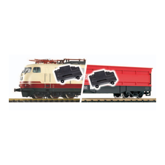
- Page 1 Montageset PIKO BR 103 Mounting kit PIKO BR 103 2/pack (8440090) Montageset LGB 41615 Mounting kit LGB 41615 1/pack (8440091)
-
Page 2: Table Of Contents
WICHTIGER HINWEIS IMPORTANT NOTE Sehr geehrte Kunden, wir empfehlen diese Dear customer, we strongly recommend Produktdokumentation und vor allem auch that you read this manu al and the warning die Warnhinweise vor der Inbetriebnahme notes thoroughly before installing and gründlich zu lesen und diese zu Beachten. operating your decoder. -
Page 3: Einleitende Informationen Zur
Einleitende Informationen zur Introductory information for Ausrüstung der PIKO E 03/103 equipping the PIKO E 03/103 with mit Antrieben für Einholmstrom- the single arm pantograph motor abnehmer drive Um das Spur G Modell der PIKO In order to equip the scale G E03 (#37440) mit Pantografenan- Modell PIKO E03 (#37440) with trieben auszurüsten benötigen sie... -
Page 4: Vorbereitung Des Antriebs
1.2 Vorbereitung des Antriebs 1.2 Preparing the motor drive 8440012: 8440012 Entfernen sie die zum Liefer- First remove the mounting boards umfang des Antriebes 8440012 from the motor drive 8440012 (4 gehörenden Montageplatten (4 screws) and install the mounting Schrauben) und montieren sie die boards of the 8440090 on the Montageplatten aus der Packung bottom side of the motor drive... - Page 5 genommen haben entfernen sie centering pivo, illustr. 2 ) e.g. with den rot markierten Bereich (Steg a rotary tool. und Aufnahmezapfen, Abb. 2) The motor-drive which has been z. B. mittels Dremel. fitted to the new mounting board Den mit der neuen Montageplatte can now be attached to the pin on versehenen Antrieb befestigen sie on the roof of the train using three nun mit drei Schrauben auf den...
- Page 6 Abbildung 3: Steg und Schraubenaufnahme sind entfernt. Gut erkennbar ist der rote Stellhebel des Pantografen Illustration #3: Rag area and screw reception have been removed. You can see the red switch handle of the pantograph. Abbildung 4: Antrieb und Montgeplatte sind mit drei Schrauben in der Lok montiert. Die grüne Trennwand ist noch einzusetzen.
-
Page 7: Anschluss An Einen Decoder
1.4 Anschluss an einen Decoder 1.4 Connecting to a decoder Die Antriebe können nun je nach As specifically written in the verwendetem Decoder wie in der instruction manual of the panto- unter Ziffer 3 der Anleitung des graph motor drive #8440012, you Pantografenantriebes #8440012 can now connect the motor-drive, beschrieben mit Stecker, Schraub- depending on the specific decoder,... -
Page 8: Einleitende Information Zur Ausrüstung Des Lgb Selbstentla- Dewagens Mit Einem Antrieb Für Scherenstromabnehmer
Einleitende Information zur Introductory information on the Ausrüstung des LGB Selbstentla- installation of the scissor pan- dewagens mit einem Antrieb für tograph motor-drive to the LGB Scherenstromabnehmer self-unloading coach Um einen LGB Selbstentlade- In order to update the LGB self-un- wagen (41610 mit analoger loading coach (41610 with analog Automatikfunktion;... - Page 9 vorsichtig ab. Entnehmen sie nun pusher and centrically replace with den Schieber nach oben und set- the pusher from the 8440091 set. zen an dessen Stelle den Schieber Afterwards screw the top back on. aus dem Set 8440091 mittig ein. Anschließend ist der Deckel wieder aufzusetzen und zu verschrauben.
-
Page 10: Installing The Motor-Drive On The Self-Unloading Coach
Abbildung 6: Antrieb mit Montageplatte im Wagenkasten montiert. Illustration 6: The Motor-drive and the mounting board has been installed in the case. 2.3 Montage des Antriebs im 2.3 Installing the motor-drive on the Selbstentladewagen: self-unloading coach: Zerlegen sie den Wagen durch First disassemble the wagon Lösen von sechs Schrauben auf by unscrewing 6 screws on the... - Page 11 Abbildung 7: Drehen des Kontaktdrahtes um 180° Illustration 7: Turning the contact wiring by 180* damit er im Drehgestell wieder stays in the back of the bogie and hinten ist und somit durch den fits the expanded cutout. (Illustr. 7) erweiterten Schlitz passt. (Abb. 7) The Power pickup can then be Die Stromabnahme kann dann zur used to supply power to the deco-...
-
Page 12: Connecting To A (Function) Decoder
Abbildung 8: Es zeigt die erforderliche Erweiterung des Schlitzes. Nur so kann der Kontakt- draht nach dem Drehen um 180° angeschlossen werden Illustration 8: This shows the necessary expansion of the cutout. Only this way the contact wire can bee hooked up correctly after being turned by 180*. Den mit der neuen Montageplatte You can now install the motor- versehenen Antrieb befestigen... - Page 13 die Anleitung ihres Decoders. After the siding track of the de- Nachdem der Gleisanschluss des coder is connected to the current Decoders mit den stromführenden carrying wheels and the decoder Radsätzen verbunden und der De- is programmed accordingly, the coder entsprechend programmiert vehicle body may now be placed ist kann der Wagenkasten seiten- true sided onto the chassis and be...
-
Page 14: Customer Service
Fremdeingriff oder send it directly to the manufac- Veränderung des Produkts besteht turer. Return shipping charges are kein Gewährleistungsanspruch. not covered by MASSOTH. Please Der Anspruch auf Servicelei- include your proof of purchase stungen erlischt unwiderruflich. with the returned goods. Please Verschleißteile sind von der... -
Page 15: Hotline
We will be happy to answer your Rückfragen zu diesem Produkt zur questions about this product. You Verfügung. Sie erreichen uns per may reach us via eMail at: eMail unter: hotline@massoth.de hotline@massoth.de Die telefonische Hotline ist unter The phone hotline is available at +49 (0)6151-35077-38 zu +49 (0)6151-35077-38 bestimmten Zeiten geschaltet. - Page 16 Massoth Elektronik GmbH QUALITY Frankensteiner Str. 28 · D-64342 Seeheim · Germany MADE IN FON: +49 (0)6151-35077-0 · FAX: +49 (0)6151-35077-44 GERMANY eMail: info@massoth.de · www.massoth.de 991116 BDA 8440090 & 8440091 RoHS 032377o COMPLIANT 2019.11...
Need help?
Do you have a question about the PIKO BR 103 and is the answer not in the manual?
Questions and answers