Table of Contents
Advertisement
Quick Links
Advertisement
Table of Contents

Related Manuals for Westermo PS-60

Summary of Contents for Westermo PS-60
- Page 1 PS-60 Power Supply Unit...
-
Page 2: Description
Power Supply Unit PS-60 User Guide 6125-2200 1. Description PS-60 power supplies are exceptionally small yet offer superior system availability in the sub 100 W power range. Powerful – Static boost of up to 125 % (PN) for a sustained period –... - Page 3 > 60 °C Derating: 2.5 %/K Dimensions W/H/D 32 mm / 99 mm Weight 0.244 kg All technical specifications are nominal and refer to a room temperature of 25 °C and 70% relative humidity at 100 m above sea level. PS-60 User Guide 6125-2200...
-
Page 4: Table Of Contents
12.2 Rotary Selector Switch in Position >50 %, >75 % or Boost >100 %: ......31 12.3 Location and Function of the Signalling Elements .............31 12.4 Active Signal Outputs, Digital ..................32 12.4.1 Signal Level Surge Protection ................32 PS-60 User Guide 6125-2200... - Page 5 Operating Modes .......................34 13.1 Series Operation .......................34 13.2 Parallel Operation .....................34 13.2.1 Redundancy Operation ..................35 13.2.2 Increased Power ....................36 Derating ........................37 14.1 Ambient Temperature ....................37 14.2 Installation Height .....................37 PS-60 User Guide 6125-2200...
-
Page 6: Ordering Data
3. Ordering Data Description Primary-switched PS-60 power supply with screw connection for DIN rail mounting, input: single phase, output: 24 V DC / 2.5 A Type PS-60 Order Number 3125-0150 Pcs. /Pkt. Instructions Safety Manual/Installation notes for electricians Instruction Number... -
Page 7: Technical Data
During the first few microseconds, the current flow into the filter capacitors is excluded. The SCCR value (short-circuit current rating) of the power supply unit corresponds to the SCCR value of the backup fuse (see input protection table). PS-60 User Guide 6125-2200... - Page 8 Power switch Input protection equivalent ≤ 13 x I Characteristics (maximum magnetic tripping) Electric strength of the insulation Housing Type test (IEC/EN 60950-1) 4 kV AC Production test 3 kV AC Field test 2 kV AC PS-60 User Guide 6125-2200...
- Page 9 Conductor cross section, flexible 0.14 mm² ... 2.5 mm² Stranded conductor cross section with 0.25 mm² ... 2.5 mm² ferrule Conductor cross section AWG 26 ... 14 Stripping length 8 mm Tightening torque 0.5 Nm ... 0.6 Nm PS-60 User Guide 6125-2200...
- Page 10 Conductor cross section, flexible 0.14 mm² ... 2.5 mm² Stranded conductor cross section with 0.25 mm² ... 2.5 mm² ferrule Conductor cross section AWG 26 ... 14 Stripping length 8 mm Tightening moment 0.5 Nm ... 0.6 Nm PS-60 User Guide 6125-2200...
- Page 11 Weight 0.244 kg Power dissipation 120 V AC 230 V AC Maximum power dissipation < 1 W < 1 W in no-load condition Power loss nominal load < 5 W < 5 W max. PS-60 User Guide 6125-2200...
- Page 12 Safety of power supply units up to 1100 V DIN EN 61558-2-16 (insulation distances) Electrical safety (of control and regulation IEC 61010-1 devices) SELV IEC 61010-1 (SELV) IEC 61010-2-201 (PELV) Safe isolation IEC 61558-2-16 IEC 61010-2-201 PS-60 User Guide 6125-2200...
- Page 13 Approvals UL Listed UL 61010-1 UL Listed UL 61010-2-201 UL 1310 Class 2 Power Units CB-Scheme (IEC 61010-1, IEC 61010-2-201) Current approvals/permissions for the product can be found in the download area under https://www.westermo.com/products/accessories/power-supplies/ps-60 PS-60 User Guide 6125-2200...
- Page 14 4 kV (Test Level 4 - asymmetrical) asymmetrical) Output 0.5 kV (Test Level 2 - 1 kV (Test Level 3 - symmetrical) symmetrical) 0.5 kV (Test Level 1 - 2 kV (Test Level 3 - asymmetrical) asymmetrical) PS-60 User Guide 6125-2200...
- Page 15 40 %, 5, 10, 50 periods (Test Level 2) (Test Level 2) Comments Criterion C Criterion B Voltage dip 0 %, 1 period 0 %, 0,5, 1, 5, 50 periods (Test Level 2) (Test Level 2) Comments Criterion B Criterion B PS-60 User Guide 6125-2200...
- Page 16 Temporary impairment to operational behavior that is corrected by the device itself. Criterion C Temporary adverse effects on the operating behavior, which the device corrects automatically or which can be restored by actuating the operating elements. PS-60 User Guide 6125-2200...
-
Page 17: Safety And Installation Notes
Never carry out work when voltage is present. Establish connection correctly and ensure protection against electric shock. Cover termination area after installation in order to avoid accidental contact with live parts (e. g., installation in control cabinet). PS-60 User Guide 6125-2200... - Page 18 The power supply is maintenance-free. Repairs may only be carried out by the manufacturer. The warranty no longer applies if the housing is opened. The power supply may only be used for its intended use. PS-60 User Guide 6125-2200...
-
Page 19: High-Voltage Test (Hipot)
Avoid unnecessary loading or damage to the power supply due to excessive test voltages. For the relevant applicable test voltages and insulation distances, refer to the corresponding table (see technical data: electric strength of the insulation section). PS-60 User Guide 6125-2200... - Page 20 Figure 1 Potential-related wiring for the high-voltage test Designation Color coding Potential levels DC output circuit Blue Potential 1 Signal contacts Blue Potential 1 High-voltage tester AC input circuit Potential 2 PS-60 User Guide 6125-2200...
-
Page 21: Structure Of The Power Supply
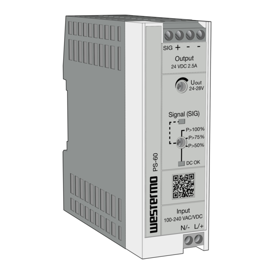
Signalling DC OK LED Rotary selector, status of the output voltage (DC OK) or output power (POut > PThr) Signalling POut > PThr LED (yellow): output power POut > output power threshold PThr Potentiometer output voltage PS-60 User Guide 6125-2200... -
Page 22: Device Dimensions
7.2 Device Dimensions Figure 3 Device dimensions (dimensions in mm) Figure 4 Device dimensions (dimensions in mm) PS-60 User Guide 6125-2200... -
Page 23: Keep-Out Areas
7.3 Keep-Out Areas Figure 5 Device dimensions and minimum keep-out areas (in mm) The minimum clearance to other devices to the left and right is 0mm. PS-60 User Guide 6125-2200... -
Page 24: Block Diagram
7.4 Block Diagram Figure 6 Block diagram PS-60 User Guide 6125-2200... -
Page 25: Mounting/Removing The Power Supply
Carefully swivel the power supply forward (C) so that the lock slides back into the starting position. Then separate the power supply from the DIN rail (D). Figure 8 Removing the power supply from the DIN rail PS-60 User Guide 6125-2200... -
Page 26: Fix Connection Wiring To The Power Supply
Figure 10 Secure connection wiring with cable binder Shorten the excess length of the cable binder ends. Then check again that the connection wiring is properly secured. PS-60 User Guide 6125-2200... - Page 27 NOTE: Mechanical damage to the connection wiring caused by friction in extreme ambient conditions, e.g., strong vibrations, protect the connection wiring against mechanical damage using additional insulation material. The additional insulation material for protecting the connection wiring is limited to the area where the cable binders are attached. PS-60 User Guide 6125-2200...
-
Page 28: Device Connection Terminal Blocks
The line protection on the primary side is suitable for this (see technical data section). DANGER: Hazardous voltage An all-pos. fuse must be present for operation on three-phase and DC systems. Protection for AC supply PS-60 User Guide 6125-2200... -
Page 29: Output
If sufficiently long connecting cables are used, fuse protection does not have to be provided for each individual load. If each load is protected separately with its own protective device, the selective shutdown in the event of a fault enables the system to remain operational. PS-60 User Guide 6125-2200... -
Page 30: Output Characteristic Curves
For fast energy storage charging (e.g., of batteries) to supply a wide range of loads. The power supply operates in the nominal operating range. Energy supply to the load is ensured. Figure 15 U/I output characteristic curve PS-60 User Guide 6125-2200... -
Page 31: Boost Currents
Dynamic boost (IDyn.Boost) delivers up to 200% of the power supply nominal current to supply high loads. This temporary power supply to the load lasts a maximum of 5 s at an ambient temperature of up to 60°C. Figure 17 Basic curve of the dynamic boost process PS-60 User Guide 6125-2200... -
Page 32: Signalling
12.3 Location and Function of the Signalling Elements Figure 18 Position of signalling elements Signalling elements LED status indicator DC OK LED on: UOut > 90% x USet LED flashing: UOut < 90% x USet LED POut > PThr Active signal output PS-60 User Guide 6125-2200... -
Page 33: Active Signal Outputs, Digital
Signal connections must satisfy the immunity requirement. Equipment that is installed in "protected" areas and has direct connections to other areas must satisfy the immunity criteria. Use surge protection when you are using signal connection types p, l, f, and h for the signal paths. PS-60 User Guide 6125-2200... - Page 34 Use surge protection when you are using connection terminal blocks "3.1 SIG" and "2.2 -" or "2.3 -" for the signals. (see Section: Technical data, electromagnetic compatibility table) Figure 21 Schematic diagram, signal wiring with surge protection PS-60 User Guide 6125-2200...
-
Page 35: Operating Modes
4. Using the same cable lengths for the DC convergence point 5. Operating power supplies in the same temperature environment 6. When three or more power supplies are connected in parallel, each output must be protected (e.g., with circuit breakers or decoupling modules) PS-60 User Guide 6125-2200... -
Page 36: Redundancy Operation
Using the signalling settings, you can monitor whether both power supplies are being operated with ≤ half the nominal load. In the case of system extension, an overload is prevented if one of the power supplies fails. PS-60 User Guide 6125-2200... -
Page 37: Increased Power
When three or more power supplies are connected in parallel, each output must be protected separately, e.g., by a circuit breaker or decoupling module. Figure 25 Schematic diagram of increased performance PS-60 User Guide 6125-2200... -
Page 38: Derating
14. Derating The PS-60 power supply runs in nominal operation without any limitations. For operation outside the nominal range, the following points should be observed depending on the type of use. 14.1 Ambient Temperature When operating the power supply at an ambient temperature of > 60°C, a power derating of 2.5%/K should be observed. - Page 39 Westermo • SE-635 35 Stora Sundby, Sweden Tel +46 16 42 80 00 Fax +46 16 42 80 01 E-mail: info@westermo.com www.westermo.com REV. A 6125-2200 2020-10 Westermo Network Technologies AB, Sweden...
Need help?
Do you have a question about the PS-60 and is the answer not in the manual?
Questions and answers