
Subscribe to Our Youtube Channel
Summary of Contents for Berger Lahr WS5-5 Series
- Page 1 Power Drive WS5-5 Doc. no. 211.347/DGB 08.02 Ident–No. 00441108390 Edition: b023 08.02...
- Page 2 Suggestions Corrections BERGER LAHR GmbH&Co.KG WS5-5 Power Drive Breslauer Str. 7 Postfach 1180 D-77901 Lahr Issue: b023 08.02 Doc. no. 211.347/DGB 08.02 Sender If you have found any faults within this documentati- on, or have any suggestions, we cordially invite you Name: to inform us on this form.
- Page 3 The warranty is invalidated in case of unauthorized modification or opening of the device. • Please ask your BERGER LAHR technical consultant prior to installing accessories not listed in the chapter "Description of accessories". The address is to be found on the rear cover.
-
Page 5: Table Of Contents
Table of Contents General Description Construction and characteristics Application/system integration Function Technical data 1.4.1 Electrical data 1.4.1.1 Mains connection 1.4.1.2 Motor connection 1.4.1.3 Signal connection of signal interface 1 1.4.1.4 Signal connection of signal interface 2 1.4.1.5 Equipment protection 1.4.2 Mechanical data 1.4.3 Ambient conditions... - Page 6 Table of Contents Errors / Faults Status indicator Troubleshooting table Storage and shipping Maintenance Appendix Description of accessories 6.1.1 Motor cable 6.1.2 Mains filter 6.1.3 Signal cable signal interface 1 6.1.4 Signal cable signal interface 2 Glossary of technical terms Index WS5-5 Doc.
-
Page 7: General Description
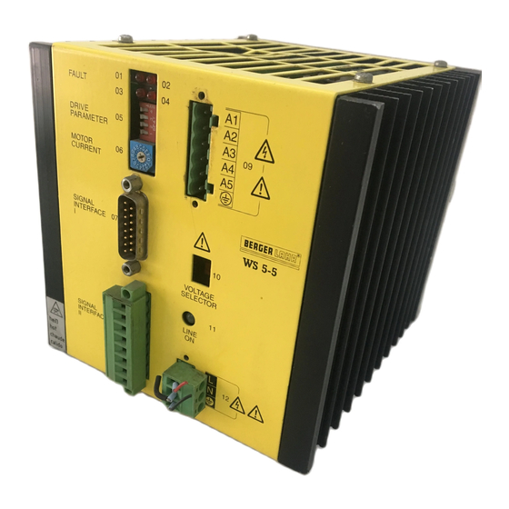
General Description General Description Construction and Characteristics Construction Characteristics The power drive WS5-5 has the following compo- The power drive WS5-5 has been designed to be nents (Figure 1-1): fixed to a mounting rail, i.e.: • Current selection switch for selecting the motor •... -
Page 8: Application/System Integration
General Discription Other characteristics include: • Operation with mains power supply; • Short-circuit protection of the power stage when there is shorting between motor phases; • Drive via signal interface 1 (with RS 422 signal levels) and/or signal via interface 2 (with PLC levels) •... -
Page 9: Function
General Description Function Figure 1-3 shows the most important function blocks of the unit: • From the mains voltage of 230 V AC or 115 V • The "control electronics - power stage - current AC the intermediate circuit voltage of 70 V DC is controller"... -
Page 10: Technical Data
General Discription Technical Data 1.4.1 Electrical data 1.4.1.4 Signal connection of signal interface 2 1.4.1.1 Mains connection Signal levels are designed for driving by PLC standard signals; there is no electrical separation Mains connection voltage, of the inputs and outputs from the motor voltage. switchable to: 115 V AC, -20% +15% The earth (GND) is connected internally to the... -
Page 11: Mechanical Data
General Description 1.4.2 Mechanical data Dimensions (L x W x H) 135 x 135 x 157 mm Weight 2.8 kg 230 V Figure 1-4 Dimensions of the equipment WS5-5 Doc. no. 211.347/DGB 12.92 1 – 5... -
Page 12: Ambient Conditions
General Discription 1.4.3 Ambient conditions Ambient temperature: Working 0°C to 50°C Storage/transportation -25°C to 70°C Change in ambient temperature: Working max. 10 K/h Storage/transportation max. 20 K/h Humidity class - components F as per DIN 40040 Humidity class tested according to IEC 68 part 2-3 •... -
Page 13: Installation
Installation Installation Parts Specification The specification must be checked for complete- ness. The specification includes (Figure 2-1) comprises: Q’ty Description Order number WS5-5.281-00 64652810006 Plug shell Mains 98050060642 connection Plug shell Motor 98050060600 connection Plug shell for 98050060642 signal interface 2 Sub-D socket 98050060558 (15 pole) -
Page 14: Accessories
Installation Accessories The following accessories can be supplied by special order: Description Order number Signal cable for signal see Appendix interface 1 Signal cable for signal see Appendix interface 2 Motor cable see Appendix Stepping motor see catalogue Doc. no. 350 End bracket EW 35 038356 from Fa. -
Page 15: Mounting
Installation Mounting CAUTION The WS5-5 must be housed in a [˚C] switch cabinet so as to ensure resist- ance to interference and prevent the Forced cooling ≥ 1 m/s equipment from being contaminated. Make sure that there are adequate pro- Convection cooling visions for the dissipation of heat! The equipment is fitted to a supporting rail on the... -
Page 16: Connection Of The Motor
Installation 2.4.2 Connection of the motor 1. Prepare the 5 wires of the motor cable and the screen which are to be connected to the plug yellow Phase 1 end with boot lace ferrules. blue Phase 2 2. Insert the 6 wires into cap of the mating plug as orange Phase 3 shown in Figure 2-4 and tighten the screws. -
Page 17: Adjustment Of The Equipment To Mains Voltage
Installation 2.4.3 Adjustment of the equipment to mains voltage The equipment can be adjusted to mains voltages 115 V AC or 230 V AC. 1. Disconnect mains voltage to the WS5-5. 230 V Voltage Switch 2. Using a screw driver, for example, turn voltage switch 10 into the desired position: switch at top: 115 V AC switch at bottom: 230 V AC. -
Page 18: Connection Of The Signal Cables
Installation 2.4.5 Connection of the signal cables Signal cable of signal interface 1 1. Twist the wires of the signal cable for signal interface 1 in pairs and solder to the terminals of PULSE PULSE the 15-pole sub-D socket connector strip as DIRECTION shown in Figure 2-8. -
Page 19: Wiring Of The Signal Interfaces
Installation 2.4.6 Wiring of the signal interfaces The WS5-5 is activated by an external controller via NOTE signal interface 1 and/or 2. The inputs of the RS 422 interface may also be driven via open-collector The two interfaces differ with respect to their pin as- outputs;... - Page 20 Installation Signal interface 2 The input level of signal interface 2 corresponds to the PLC standard. The drive may be provided by any commercial PLC. Inputs 1, 2, 3 = 0 V to 3 V S low = 13 V to 0 V S high ≥...
-
Page 21: Examples For Application
Installation 2.4.7 Examples for application 2.4.7.1 Basic driving possibilities Interface 1: npn-drive Interface 1: pnp-drive WS5-5 Driving side WS5-5 Driving side +24 V Sub-D-socket Sub-D-socket +24 V Pulse Direct. 2,4k 2,4k +PULSE +PULSE - PULSE - PULSE +DIRECTION +DIRECTION - DIRECTION - DIRECTION +ENABLE +ENABLE... -
Page 22: Driving The Ws5-5 Via Positioning Unit From Berger (Wp111, Wp311)
Installation 2.4.7.2 Driving the WS5-5 via positioning unit from BERGER (WP111, WP311, WPM311) Interface 1 Interface 2 Positioning unit WP111, WP311, WPM311 WS5-5 Sub-D-socket Sub-D-socket WS5-5 +PULSE - READY - PULSE +READY +DIRECTION Signal interface 2 is - DIRECTION - ZERO PHASE +ENABLE ENABLE not connected. -
Page 23: Driving Of Two Ws5-5 Via Wp111 Positioning Unit From Berger
Installation 2.4.7.3 Driving of two WS5-5 via WP111 positioning unit from BERGER If two WS5-5 power drives are driven via a position- NOTE ing unit WP111, the WS5-5 are to be connected in Resistance to interference of data parallel. transfer is reduced, if a cable without screening is used to drive the WS5-5. -
Page 24: Driving Of Two Ws5-5 Via Wp311 Positioning Unit From Berger
Installation 2.4.7.4 Driving of two WS5-5 via WP311 positioning unit from BERGER Two WS5-5 can be driven via a positioning unit WP311 in the same way as via a WP111, see chap- ter 2.4.7.3. Interface 1 Positioning unit WP311 WS5-5 (axis 1) WS5-5 (axis 2) Sub-D-socket Sub-D-socket... - Page 25 Installation 2.4.7.5 Driving via PCL IP 267 from Siemens Interface 1 Interface 2 WS5-5 Siemens PLC IP 267 Sub-D-socket WS5-5 Sub-D pin contact strip +PULSE To PLC input - READY - PULSE +READY +24 V +DIRECTION - DIRECTION - ZERO PHASE +ENABLE +ZERO PHASE - ENABLE...
-
Page 26: Initial Operation
Installation Setting of the phase current Initial Operation Setting the phase current using rotary switch 06. 2.5.1 Checklist for initial operation For the possible settings, see Figure 2-20. If it is Before you start to make the basic settings to the found to be impossible to set the phase current indi- equipment, check the following points: cated on the rating plate of the motor, set the next... - Page 27 Installation Setting of the parameters Use the DIL switch 05 to set desired parameters as illustrated in Figure 2-21. The basic factory setting is indicated. NOTES • The function of the signal input PWM/BOOST is defined by the switch position of the Current con- trol/Boost.
- Page 28 Installation 2 – 16 WS5-5 Doc. no. 211.347/DGB 03.96...
-
Page 29: Operation
Operation Operation The power drive WS5-5 is operated by means of control signals. It can be linked to the external con- troller via signal interfaces 1 and/or 2. Signal Description The meanings and functions of the individual sig- nals are described below. 3.1.1 Input signals NOTE... - Page 30 Operation ENABLE (Enabling Command) • Input ’active’: enabling of power drive ENABLE • Input ’inactive’: deletion of a stored fault report READY (see section 4.2) and resetting of the ring coun- ter (see output signal 0-PHASE). The motor is disconnected from the current. <...
-
Page 31: Output Signals
Operation 3.1.2 Output signals NOTE ’Active’ output means low-impedance. ’Inactive’ output means high-imped- ance. READY When the output is ’active’, the power stage of the WS5-5 is operative (see Figure 3-2). 0-PHASE (ring counter reading zero) Each time the ring counter reading is zero, this out- put is switched to ’active’... -
Page 32: Switching On
Operation Switching On Switch on mains voltage at external switch. After the mains voltage has been switched on, the green LED on the front panel of the equipment lights up and signals that the supply voltage is pres- ent at WS5-5. If no red LED lights up on the front panel, the power stage of the WS5-5 is ready, i.e. -
Page 33: Errors / Faults
Errors / Faults Errors / Faults Status Indicator Several monitoring and protection functions are The table indicates the possible statuses of the used to establish whether the equipment is opera- equipment and the respective consequences for the ting correctly. The status of the equipment is exter- equipment outputs. -
Page 34: Troubleshooting Table
Errors / Faults Troubleshooting Table Indicator Status Possible cause of fault Remedy Undervoltage Mains voltage too low Switch off the equipment! Voltage switch in 230 V AC position and Set the correct voltage equipment is being on the voltage switch operated with 115 V AC Phase interruption Interruption of one or... -
Page 35: Storage And Shipping
Errors / Faults Storage and Shipping When equipment or insert cards are stored the fol- When equipment and insert cards are shipped, the lowing points have to be taken into consideration: following points have to be taken into consideration: • the maximum humidity (see Technical Data) is •... - Page 36 Errors / Faults 4 – 4 WS5-5 Doc. no. 211.347/DGB 12.92...
-
Page 37: Maintenance
Maintenance Maintenance WS5-5 requires no maintenance. WS5-5 Doc. no. 211.347/DGB 12.92 5 – 1... - Page 38 Maintenance 5 – 2 WS5-5 Doc. no. 211.347/DGB 12.92...
-
Page 39: Appendix
Appendix Appendix Description of Accessories Power controller WS5-5 Stepping motor Mains IP 267, POSAB, IP 247 WP-311, WP-111 Figure 6-1 Accessories WS5-5 Doc. no. 211.347/DGB 12.92 6 – 1... - Page 40 Appendix The following accessories can be supplied by separate order: Item in Description Order number Reference Figure 6-1 Motor cable 62501316xxx see section 6.1.1 Mains filter 62501100200 see section 6.1.2 Signal cable signal interface 1 see section 6.1.3 for IP 247 or 62501413xxx for IP 267 62501414xxx...
-
Page 41: Motor Cable
Appendix 6.1.1 Motor cable Ambient conditions The motor cable can be supplied in the following Storage temperature -25°C to +70°C lengths: Operating temperature 0°C to 55°C Cable length Diameter Order number Humidity class, components F acc. to DIN 40 040 0.75 mm 62501316005 Humidity class, tested to IEC 68 part 2-3 at:... - Page 42 Appendix An 8-pole screened cable can be supplied for signal interface 2 (Order number: 98078305072). NOTE The desired cable length must be stated when placing the order. 6 – 4 WS5-5 Doc. no. 211.347/DGB 12.92...
-
Page 43: Glossary Of Technical Terms
Negative sense of rotation as seen from the motor shaft (flange side) ENABLE command Signal input for activation of the controller 5-phase stepping motor Special stepping motor for wall- mounted equipment from BERGER LAHR Full step Rotational angle of the 5-phase stepping motor per 0.72" step (corresponds to 500 steps/revolution) Half step Rotational angle of the 5-phase stepping motor per 0.36"... -
Page 44: Index
Index Index Page Page Ambient conditions Mains connection Ambient temperature Mains power unit 1-3, 1-4 Mains voltage 1-4, 2-5 Minimum clearance Monitoring function 1-4, 4-1 Boost 1-3, 2-14f, 3-1f Motor Motor connection 1-4, 2-4 Motor cable 2-4, 6-3 Connections 1-1, 2-4ff Current pattern Current reduction 2-14f... - Page 45 Index Page Technical data 1-4ff Troubleshooting Voltage switch 1-1, 2-5 Weight 7 – 2 WS5-5 Doc. no. 211.347/DGB 12.92...
Need help?
Do you have a question about the WS5-5 Series and is the answer not in the manual?
Questions and answers