Table of Contents
Advertisement
Advertisement
Table of Contents

Subscribe to Our Youtube Channel
Summary of Contents for Brofer MDF25L
- Page 1 INSTALLATION AND OPERATION MANUAL FIRE PROTECTION MDF25L making air better...
- Page 2 FIRE DAMPERS CERTIFIED ACCORDING TO EN 15650 SERIE MDF25L 0497/CPR/5136 INDEX SPECIFICATIONS/GENERAL INFORMATION pag 3 NORMATIVE REFERENCES PRECAUTIONS FOR HANDLING AND INSTALLATION MAINTENANCE WALL INSTALLATION CEILING INSTALLATION LIGHT WALL INSTALLATION SUGGESTIONS OPERATING CONTROLS 10. MECHANICAL FUSE REPLACEMENT 11. OPERATION DATA AND WIRING MANUAL CONTROLS...
-
Page 3: Specifications/General Information
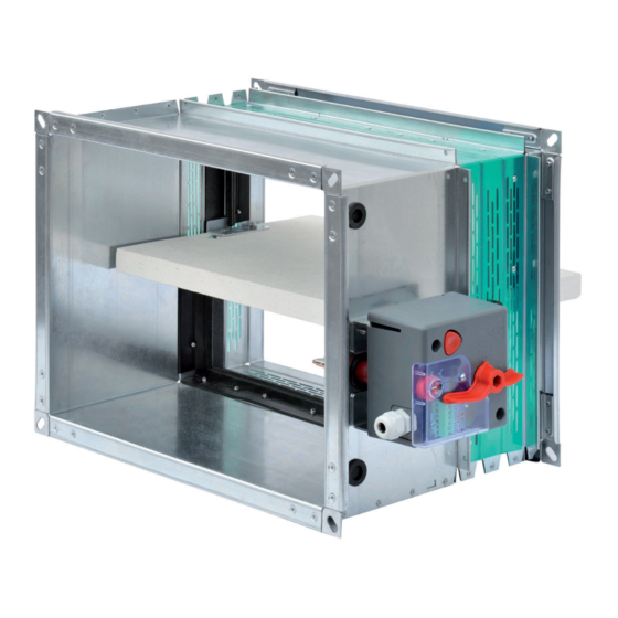
1. SPECIFICATIONS/GENERAL INFORMATION Fire damper suitable for installation on a wall, light wall and ceiling made from duct and galvanized steel compo- nents, calcium silicate blade mono slab sp. 25 mm with perimeter seals to ensure sealing requirements to cold and hot smoke. -
Page 4: Maintenance
3. PRECAUTIONS FOR HANDLING AND INSTALLATION CAUTION! • All operations of handling and installation shall be made with the blade of the fire damper in the closed position (our standard delivery). • All operations of connection power line must be performed by qualified service personnel. •... -
Page 5: Wall Installation
5. WALL INSTALLATION 1 Before proceeding with the installation, verify the integrity of the damper, the correct positioning of the blade in the closed position and operation of the command. 2 Provide an opening in the wall (Figure 1) having larger dimensions than the nominal size of the damper (see table 1 according to the type of installation). - Page 6 7. LIGHT WALL INSTALLATION 1 Before proceeding with the installation, verify the integrity of the damper, the correct positioning of the blade in the closed position and operation of the command. 2 Provide an opening in the wall (fig.1A) having larger dimensions than the nominal size of the damper (see table 1 according to the type of installation).
-
Page 7: Command Operation
9. COMMAND OPERATION Manual command Rearmament: • From the unlocked position (Figure 4), where the indicator on the rearmament lever is positioned on the symbol] - [, turn the lever 90 ° clockwise making sure that the command locks into place opening (fig.5 ), the indicator is located on the lever on the symbol] I [. - Page 8 • Unscrew the 2 screws and remove the release mechanism from the plate. Vite di fissaggio Fig. 11 meccanismo fig. 12 • Replace the fuse by compressing the di rilascio spring and hooking the two protru- Fig. 12 ding pins (fig. 12). brofer.it pag. 6/7...
- Page 9 11. OPERATION DATA AND WIRING MANUAL CONTROLS Microswitches start and end of stroke The signaling devices stroke end FCU and beginning stroke DCU are both switches with two contacts independent of the type NC + NO. The first nor- mally closed (NC) contacts 1 and 6, while the second normally open (NO) contacts 2 and 5.
- Page 10 12. OPERATION DATA AND WIRING MOTORIZED CONTROLS The operation of the motor is given by the connection to the electricity network (contacts 1 and 2) which brings the blade of the damper in the open position and simultaneously charging the internal spring which stores the force re- quired to close the duct in case of alarm or black- outs.
- Page 12 BROFER SRL - Via Roma, 66 - 31023 Resana (TV) Italy Tel. +39 0423 716611 - Fax +39 0423 716612 - info@brofer.it - www.brofer.it Μιχαήλ Καραολή 19 143 43, Ν. Χαλκηδόνα, Αθήνα, Τηλ: 211 - 70.55.500 & 210 - 21.30.051, Fax: 210 - 22.23.283...
Need help?
Do you have a question about the MDF25L and is the answer not in the manual?
Questions and answers