Table of Contents
Advertisement
Quick Links
Advertisement
Table of Contents

Related Manuals for SK Pang Electronics RSP-PICAN3

Summary of Contents for SK Pang Electronics RSP-PICAN3
- Page 1 PiCAN 3 Rev C 1.0 PiCAN3 CAN-Bus with 3A SMPS + RTC USER GUIDE V1.0 Product name PiCAN3 CAN-Bus Board for Raspberry Pi 4 with 3A SMPS + RTC Model number RSP-PICAN3 Manufacturer SK Pang Electronics Ltd SK Pang Electronics Ltd © 2019 www.skpang.co.uk...
-
Page 2: Table Of Contents
PiCAN 3 Rev C 1.0 Contents Table of Contents 1. Introduction ......................3 1.1. Features ................................3 Hardware Installation ....................3 1.2. Configuring DB9 Connector ......................... 4 1.3. OBDII Cable ................................. 4 1.4. CAN Cable ................................4 1.5. Screw Terminal ..............................5 1.6. 120Ω Terminator ............................. 5 1.7. LED ..................................5 3. Software Installation ....................5 1.8. Installing CAN Utils ............................6 1.9. Bring Up the Interface ............................ 6 Real Time Clock (RTC) Software Installation ............. 7 Python Installation and Use ..................9 SK Pang Electronics Ltd © 2019 www.skpang.co.uk... -
Page 3: Introduction
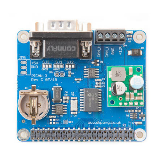
PiCAN 3 Rev C 1.0 1. Introduction his PiCAN2 board provide CAN-Bus capability for the Raspberry Pi 4. It uses the Microchip MCP2515 CAN controller with MCP2551 CAN transceiver. Connection are made via DB9 or 3 way screw terminal. This board includes a 3A switch mode power suppler that powers the Pi is well. Easy to install SocketCAN driver. Programming can be done in C or Python. 1.1. Features • CAN v2.0B at 1 Mb/s • High speed SPI Interface (10 MHz) • Standard and extended data and remote frames • CAN connection via standard 9-way sub-D connector or screw terminal • Compatible with OBDII cable • Solder bridge to set different configuration for DB9 connector • 120Ω terminator ready • Serial LCD ready • LED indicator • Foot print for two mini push buttons • Four fixing holes, comply with Pi Hat standard • SocketCAN driver, appears as can0 to application • Interrupt RX on GPIO25 • 5v 3A SMPS to power Raspberry Pi and accessories from DB9 or screw terminal o Reverse polarity protection o High efficiency switch mode design o 6v to 20v input range •... -
Page 4: Configuring Db9 Connector
PiCAN 3 Rev C 1.0 1.2. Configuring DB9 Connector The CAN connection can be made via the DB9 connector. The connector be configured for different pinout. Depend if you are using an OBDII cable or a CAN cable. 1.3. OBDII Cable Close the solder bridges on the lefthand side on SJ1, SJ2 and SJ3 as shown with a red line. DB9 Pin Function number GND CAN_H CAN_L 1.4. CAN Cable Close the solder bridges on the righthand side on SJ1, SJ2 and SJ3 as shown with a green line. DB9 Pin Function number GND CAN_H CAN_L SK Pang Electronics Ltd © 2019 www.skpang.co.uk... -
Page 5: Screw Terminal
PiCAN 3 Rev C 1.0 1.5. Screw Terminal The CAN connection can also be made via the 4 way screw terminal. Pin number Function CAN_H CAN_L GND +12v In 1.6. 120Ω Terminator There is a 120Ω fitted to the board. To use the terminator solder a 2way header pin to JP1 then insert a jumper. 1.7. LED There is a red LED fitted to the board. This is connected to GPIO22. 3. Software Installation It is best to start with a brand new Raspbian image. Download the latest from: https://www.raspberrypi.org/downloads/raspbian/ After first time boot up, do an update and upgrade first. sudo apt-get update sudo apt-get upgrade sudo reboot SK Pang Electronics Ltd © 2019 www.skpang.co.uk... -
Page 6: Installing Can Utils
PiCAN 3 Rev C 1.0 Add the overlays by: sudo nano /boot/config.txt Add these 3 lines to the end of file: dtparam=spi=on dtoverlay=mcp2515-can0,oscillator=16000000,interrupt=25 dtoverlay=spi-bcm2835-overlay Reboot Pi: sudo reboot 1.8. Installing CAN Utils Install the CAN utils by: sudo apt-get install can-utils 1.9. Bring Up the Interface You can now bring the CAN interface up at 500kbps: sudo /sbin/ip link set can0 up type can bitrate 500000 To send a CAN 2.0 message use : cansend can0 7DF#0201050000000000 SK Pang Electronics Ltd © 2019 www.skpang.co.uk... -
Page 7: Real Time Clock (Rtc) Software Installation
PiCAN 3 Rev C 1.0 Connect the PiCAN to a CAN-bus network and monitor traffic by using command: candump can0 You should see something like this: 4. Real Time Clock (RTC) Software Installation Insert a CR1220 battery (not supplied) into battery holder. Ensure the “+” is facing upward. Install the i2c-tools by: sudo apt-get install i2c-tools Then check the RTC: sudo i2cdetect -y 1 You should see 68 or UU on address 0x68: SK Pang Electronics Ltd © 2019 www.skpang.co.uk... - Page 8 PiCAN 3 Rev C 1.0 Add the overlays by: sudo nano /boot/config.txt Add these lines to the end of file: dtparam=i2c_arm=on dtoverlay=i2c-rtc,pcf8523 Reboot Pi: sudo reboot Now you need to disable the "fake hwclock" which interferes with the 'real' hwclock sudo apt-get -y remove fake-hwclock sudo update-rc.d -f fake-hwclock remove sudo systemctl disable fake-hwclock Start the original hw clock script by: sudo nano /lib/udev/hwclock-set and comment out these three lines: #if [ -e /run/systemd/system ] ; then # exit 0 and comment out these two lines: #/sbin/hwclock --rtc=$dev --systz --badyear #/sbin/hwclock --rtc=$dev --systz...
-
Page 9: Python Installation And Use
PiCAN 3 Rev C 1.0 Reboot the Pi. Ensure the Ethernet cable or Wifi is on. This will get the time from the network. Set the clock by: sudo hwclock -w To read the clock: sudo hwclock -r 5. Python Installation and Use Ensure the driver for PiCAN 3 board is installed and working correctly first. Clone the pythonCan repository by: git clone https://github.com/hardbyte/python-can cd python-can sudo python3 setup.py install Check there is no error been displayed. SK Pang Electronics Ltd © 2019 www.skpang.co.uk... - Page 10 PiCAN 3 Rev C 1.0 Bring up the can0 interface: sudo /sbin/ip link set can0 up type can bitrate 500000 Now start python3 and try the transmit with CAN frame. python3 To sent a message out type the following lines: import can bus = can.interface.Bus(channel='can0', bustype='socketcan_native') msg = can.Message(arbitration_id=0x7de, data=[0, 25, 0, 1, 3, 1, 4, 1], extended_id=False) bus.send(msg) To received messages and display on screen type in: notifier = can.Notifier(bus, [can.Printer()]) SK Pang Electronics Ltd © 2019 www.skpang.co.uk...
Need help?
Do you have a question about the RSP-PICAN3 and is the answer not in the manual?
Questions and answers