Table of Contents
Advertisement
Quick Links
Advertisement
Table of Contents

Summary of Contents for Carl Roth VioLab 50 Series
- Page 2 UM Serie 50VioLab EN rev.1 19.05.2020...
- Page 3 Index Introduction Safety information Definitions of warning words and symbols Reporting terms Additional documents for safety Use according to destination Basic requirements for a safe use Unauthorized use Device maintenance Responsibility of the owner of the instrument Instrumental features ...
- Page 4 ORP Parameter (Redox Potential) ORP Parameter Setup ORP automatic calibration Conductivity Parameter …how to get Conductivity? Setup for Conductivity Parameter Automatic COND calibration Manual COND calibration Errors during calibration Performing Conductivity measurement TDS Parameter Instrument Setup Menu Warranty...
- Page 5 Introduction XS Instruments, globally recognized as a leading brand in the field of electrochemical measurements, has developed this new line of professional bench instruments, which is completely produced in Italy, finding the perfect balance between performance, attractive design and ease of use. The perfect balance between the high performance of the instrument, a modern and attractive design and the user-friendliness make this series of instruments the ideal solution for electrochemical measurements in laboratory.
-
Page 6: Safety Information
Safety information Definitions of warning words and symbols This manual contains extremely important safety information, in order to avoid personal injury, damage to the instrument, malfunctions or incorrect results due to failure to comply with them. Read entirely and carefully this manual and be sure to familiarize with the tool before starting to work with it. -
Page 7: Use According To Destination
Additional documents for safety The following documents can provide the operator with additional information to work with the measuring system safely: operating manual for electrochemical sensors; safety data sheets for buffer solutions and other maintenance solutions (e.g. storage); ... - Page 8 Responsibility of the owner of the instrument The person who owns and uses the tool or authorizes its use by other people is the owner of the tool and is responsible for the safety of all users of the tool and third parties. The owner of the instrument must inform users of the use of the same safely in their workplace and on the management of potential risks, also providing the required protective devices.
-
Page 9: Data Sheet
Datasheet Series 50 VioLab pH 50 VioLab - PC 50 VioLab Measuring range 0 … 14 Resolution / Accuracy 0.1, 0.01 / +0.02 Recognized calibration points and AUTO: 1…3 / USA, NIST CUS: 2 user values buffers Buffers indication Calibration Report DHS sensor recognition Low –... -
Page 10: Instrument Description
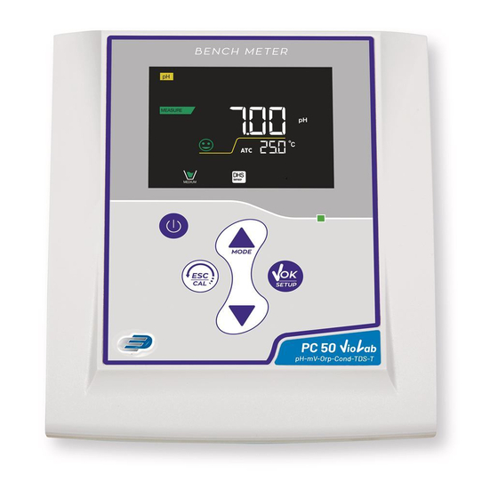
Instrument description Display Error symbol Measurement parameter Date and time Text string Battery charge level Indication of instrumental mode Actual value / Measure unit Stability indicator Temperature and type of Text string compensation ATC - automatic NTC 30KΩ MTC - manual Representation of buffers used for calibration DHS connection icon... -
Page 11: Installation
Installation Supplied components The instrument is always supplied with all the accessories necessary for being put into service; the version without sensor is always supplied with: instrument complete with multi-socket adapter, 1m S7/BNC connection cable, NT55 temperature probe, buffer solutions in single-dose bottle and / or sachet, electrode holder stand, multilingual user manual and test report. -
Page 12: Key Functions
the instrument switches on at the last parameter used. To switch off the instrument, press the key in measure mode. Instrument transportation To move the instrument to a new location, ship it carefully to avoid damage; the instrument can be damaged, if it is not transported correctly. - Page 13 Inputs / Outputs Connections Use original accessories guaranteed by the manufacturer only. If necessary, contact your local distributor. The BNC connectors are protected by a plastic cap. Remove the cap before connecting the probes. PC 50 VioLab upper panel RCA for pH Temperature RCA for Conductivity Connection to the power grid...
-
Page 14: Operation Of The Device
Operation of the device After the switching on, the instrument enters measure mode in the last parameter used. To scroll through the different parameter screens, press the key ; the current measurement parameter is shown in the display on the top left (e.g.: Sequence of parameters in measure mode: pH 50 VioLab COND 50 VioLab... -
Page 15: Setup Menu
Setup Menu In measure mode, press the key to enter SETUP mode, select the parameter you want to edit by using the directional keys and confirming with pH 50 VioLab COND 50 VioLab PC 50 VioLab PH SETTINGS COND SETTINGS PH SETTINGS ORP SETTINGS TDS SETTINGS... - Page 16 P4.0 TDS SETTING P4.1 TDS Factor P9.0 SETTINGS P9.1 Temperature U.M. P9.4 Brightness P9.6 Parameters Setup P9.8 Reset Temperature measurement ATC – MTC ATC : The direct measurement of the sample temperature for all parameters is carried out through the NTC 30KΩ...
- Page 17 The instrument automatically recognizes 2 families of buffers (USA and NIST); in addition, the user has the option of performing a manual calibration up to 2 points with customizable values. USA Buffers: 1,68 - 4,01 - 7,00** - 10,01 (Factory setting) pH value of the Beaker NIST Buffers: 1,68 - 4,00 - 6,86** - 9,18...
- Page 18 Automatic pH calibration Example: three-point calibration with USA type buffers (7.00 / 4.01 / 10.01). In pH measure mode press the key to enter calibration mode. The string “1ST POINT PH 7.00” appears on the display; the device requires the neutral value as the first calibration point.
- Page 19 Calibration with manual values Example two-point calibration pH 6.79 e pH 4.65 (DIN19267) Access the Setup menu for pH and select in P1.1 Custom, press twice the key to return to the measurement and position in pH mode ...
-
Page 20: Errors During Calibration
Example of an unstable measurement Example of stable measurement After the measurement, wash the electrode with distilled water and preserve it in the appropriate storage solution. Never store the sensors in ANY TYPE of water OR DRY! It is a useful tool for obtaining accurate measurements always having on the display the indication of the buffers used for calibration and the possibility of consulting the calibration data, at any time, or entering the expiry date. - Page 21 mV Parameter pH 50 VioLab; PC 50 VioLab In measure mode press the key and move to the mV parameter indicated by the icon The display shows the measurement in mV of the pH sensor. The scrolling on the display of four red bands means that the measurement is not stable yet.
- Page 22 ORP automatic calibration Automatic calibration with 475 mV In ORP measurement mode press the key to enter the calibration mode. The string “POINT ORP 475” appears on the display; the device requires 475 mV as calibration point. ...
- Page 23 The table below shows the setup menu structure for the COND parameter; for each program, there are the options that the user can choose and the default value: Program Description Options Factory Default Settings P3.1 CELL CONSTANT 0.1 - 1 - 10 P3.2 CALIBRATION METHOD AUTOMATIC / CUSTOM...
- Page 24 This device measures Conductivity at real temperature (ATC or MTC) and then converts it to the reference temperature using the correction factor chosen in program P3.4. Access this setup menu to set the temperature to which you want to refer the Conductivity measurement.
- Page 25 P3.8 COND parameter Reset If the instrument does not work properly or incorrect settings have been made, confirm YES with the key to return all the parameters of the pH menu to the default settings. P3.9 Temperature calibration All the instruments in this series are pre-calibrated for a correct temperature reading. However, if there is a difference between the measured and the real one (usually due to a probe malfunction), it is possible to perform an offset adjustment of + 5°C.
- Page 26 ATTENTION: Before proceeding with the calibration operations, carefully consult the safety data sheets of the substances involved: Calibration Buffer solutions. Manual COND calibration Example: Calibration at 5.00 µS/cm using a K=0.1 cell constant Access the Setup menu for COND SETTINGS and select in the P3.1 0.1 and into the program P3.2 Custom, then go back to the measurement and go into COND mode ...
- Page 27 Performing Conductivity measurement Access the Setup menu for Conductivity to check the calibration, and if necessary, update the reading parameters; press key to return to measure mode. Press to scroll through the different screens of parameters until activating the Conductivity parameter indicated by the icon ...
-
Page 28: Instrument Setup Menu
Here below, the TDS factors in relation to the Conductivity value are shown: Conductivity of the Solution TDS Factor 1-100 µS/cm 0.60 100 – 1000 µS/cm 0.71 1 – 10 mS/cm 0.81 10 – 200 mS/cm 0.94 The TDS measurement is expressed in mg/l or g/l depending on the value. Instrument Setup Menu ... -
Page 29: Warranty
Warranty Warranty period and limitations The manufacturer of this device and its accessories offers the final consumer of the new device the three-year warranty from the date of purchase, in the event of state-of-the-art maintenance and use. During the warranty period, the manufacturer will repair or replace defective components.
Need help?
Do you have a question about the VioLab 50 Series and is the answer not in the manual?
Questions and answers