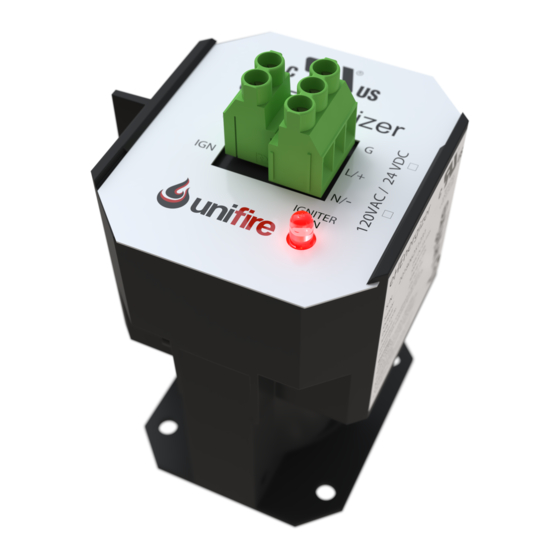
Summary of Contents for Unifire eHEnergizer PHE-24
- Page 1 eHEnergizer Installation and Operation Manual Model(s) Part Number(s) PHE-24 P-1000001-02 PHE-120 P-1000002-02 0025_PHE_IOM.pdf Rev 6...
-
Page 2: Table Of Contents
SPECIFICATION AND RATINGS ........................ 9 DIMENSIONS ............................10 INSTALLATION ............................11 ..........................12 NPACKING ........................... 12 IELD IRING 7.3.3 Igniter Tip Connection ....................... 14 ....................... 15 EMOTE IELD IRING TESTING THE SYSTEM ........................... 16 TROUBLESHOOTING ..........................17 www.unifire.ca Page email: support@unifire.ca Copyright 2017 Unifire... - Page 3 Table of Figures Figure 1 - Dimensions ........................10 Figure 2 - Explosion Proof Cover Removal ..................12 Figure 3 - PHE Wiring Schematics ....................13 Figure 4 – Typical Igniter Tip Assembly ..................14 www.unifire.ca Page email: support@unifire.ca Copyright 2017 Unifire...
-
Page 4: How To Use This Manual
1 How to Use This Manual The following symbols appear throughout Unifire installation and operation manuals. HAZARD A specific hazard is brought to the attention of the reader. Failure to observe these instructions may result in injury or other high severity consequence. -
Page 5: Limited Product Warranty
(12) months starting from the date of purchase. At the sole discretion of Unifire; the liability of Unifire shall be limited to the costs of the parts to be repaired in the defective product or to the exchange of the defective product for a replacement product. -
Page 6: Service Support And Returns
3 Service Support and Returns For service and support please contact the Unifire support team using your preferred method below. Please include the serial number on the label of the eHEnergizer in your communications to allow us to help you as quickly as possible. -
Page 7: General Product Information
After the trial for ignition period, the power can typically be removed from the unit. A BMS can do this automatically once the flame is proven. There are no additional sparks www.unifire.ca Page email: support@unifire.ca Copyright 2017 Unifire... - Page 8 HAZARD Care must be taken with the high voltage terminals at power-off. Discharge to levels below 30VDC may take up to 4 minutes. www.unifire.ca Page email: support@unifire.ca Copyright 2017 Unifire...
-
Page 9: Specification And Ratings
The PHE-120 draws an average of approximately 1.7A for 150ms when re-charging capacitors after a spark. Once the capacitors are fully charged the current draw is negligible <500mA. PHE electronic module only, not including explosion proof enclosure. www.unifire.ca Page email: support@unifire.ca Copyright 2017 Unifire... -
Page 10: Dimensions
6 Dimensions Figure 1 - Dimensions www.unifire.ca Page email: support@unifire.ca Copyright 2017 Unifire... -
Page 11: Installation
This is NOT a single wire ignition system. There must be a return wire or unimpeded ground connection between the igniter tip and terminal G on the high voltage side of the unit. Follow all local codes for proper bonding of the exciter. www.unifire.ca Page email: support@unifire.ca Copyright 2017 Unifire... -
Page 12: Unpacking
PLC). Otherwise interposing relays are required. Similarly, the PHE-120 unit can be wired as per traditional ignition transformers or via an interposing relay to the PLC. The wiring schemes are illustrated below (Figure 3). www.unifire.ca Page email: support@unifire.ca Copyright 2017 Unifire... -
Page 13: Figure 3 - Phe Wiring Schematics
A #14 AWG ground wire should also be wired to the “eHEnergizer” Ground (G) terminal. A 3A slow blow fuse should be provided in the PHE-24 power supply circuit. A 2A slow blow fuse should be provided in the PHE-120 power supply circuit. www.unifire.ca Page email: support@unifire.ca Copyright 2017 Unifire... -
Page 14: Igniter Tip Connection
The “eHEnergizer” models are compatible and have been validated for use with a variety of igniter tips. Optimized igniter tips (part number P-10000000-00 & P-10000000-01) are available from Unifire and we strongly advise that you contact us (sales@unifire.ca) to verify compatibility with your existing igniter tips. -
Page 15: Remote Field Wiring
The recommended maximum distance for remote mounting of the “eHEnergizer” is 1000ft i.e. the ignition wire should not exceed 1000ft in length. If the installation requirement cannot satisfy this please contact Unifire to understand how longer distances can be accommodated. www.unifire.ca Page email: support@unifire.ca... -
Page 16: Testing The System
6. The sparking then pauses for 10 seconds. 7. Sparking resumes for another 20seconds until removal of power. On removal of power, if power is again applied quickly (<1-2 seconds) the unit will remain in the 10 second delay period. www.unifire.ca Page email: support@unifire.ca Copyright 2017 Unifire... -
Page 17: Troubleshooting
The “eHEnergizer” contains no user serviceable parts. A shock hazard is present with the device and under no circumstances should the end-user attempt to disassemble the electronic unit. Please contact Unifire support for assistance with unit installation, operation and fault finding (support@unifire.ca). - Page 18 “jump” towards the fuel/air. Nitrogen in Lines On a first start it is common to have residual nitrogen from commissioning in the lines, try a few times to ensure that this is purged. www.unifire.ca Page email: support@unifire.ca Copyright 2017 Unifire...
- Page 19 [End of Manual] www.unifire.ca Page email: support@unifire.ca Copyright 2017 Unifire...

Need help?
Do you have a question about the eHEnergizer PHE-24 and is the answer not in the manual?
Questions and answers