
Related Manuals for Rose electronics BesCutter G Series

Summary of Contents for Rose electronics BesCutter G Series
- Page 1 BesCutter Fiber Laser Cutting Machine User Manual (Version: V6.15) Rose Graphix LLC DBA BesCutter.Com, 5490 Lee St, Lehigh Acres, FL 33971 888-525-2897...
-
Page 2: Product Overview
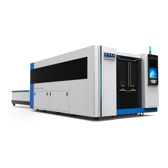
1. Preface Thank you for purchasing the G series laser cutting machine from Rose Graphix LLC. If this is your first time to use this machine, please read the manual carefully before using the machine. The content labeled "dangerous", "warning" and "attention" must be pay attention to specially to ensure the safety of your and surrounding personnel, and proper use of this equipment. - Page 3 2.2 Product characteristics and appearance Figure: The machine appearance Note: All the pictures in this manual are for reference only. (Do not include the products special instructions). The product provided the user shall be prevails a. Beams cast having double column framework layout and bed welded being large cross section, the machine is high at rigidity, stability and shock resistance.
-
Page 4: Environmental Conditions
prolong the service life. Gear and rack of X axis and Y axis are regularly lubricated by central lubrication devices; linear guide way of X axis and Y axis are lubricated by manual regular. Z axis motor is controlled by capacitive sensor to driven cutting head that moves up and down, which ensure the distance between nozzle and the plate cut to be constant to ensure the cutting quality. - Page 5 e. The machine must be grounded, grounding pile on machine side and connecting wire, to connect machine to a power wire is also allowed, and the grounding resistance should be less than 4 ohm. f. Site environment: good ventilation conditions, no dust, no corrosion, and no pollution. g.
- Page 6 G Series CNC laser cutting machine is mainly composed of the main machine, control systems, laser, chiller and exhaust fan, etc. Except for exhaust fan and chiller, others have there’s own manual. This manual mainly introduces the structure of main machine and electrical control system; the rest parts can be referred in their specification.
- Page 7 2.6.2 The structure, function, and working principle of main components or functional units 2.6.2.1 Bed Being a rectangle frame structure that is welded by high strength steel, bed is annealed to eliminate internal stress after welding and is vibrating treated after roughing. There is also vibration effectiveness after semi-finishing.
- Page 8 After the distance from the nozzle to plate surface is detected by the capacitive sensor installed in the cutting head, the signal is fed back to the control system, then the cutting head, driven by Z axis motor, moves up and down to assure the distance between the nozzle to plate unchanged and to ensure effectively cutting quality.
- Page 9 Figure: CNC operator interface a) Easy to operation There are six function soft keys and eight operational soft keys in this machine, operational soft keys have different functions in different operation mode, thereby the operating button are reduced and the operation panel is simplified. There are menu display functions in any mode, so operation is intuitive.
- Page 10 Figure: Graphic display f) Various alarm functions Having a self-test alarm system and automatic protection function, this CNC system also can do alarm display and automatic protection for external conditions.
- Page 11 Figure: Alarm functions g) The electrical control system can be divided into CypCut CNC systems, machine control panel, low voltage electrical systems, motors and machine electrical, according to its mounting position. h) CypCut CNC system Belonging to high-end system, CypCut CNC system is special CNC laser system for CNC machine tools.
- Page 12 j) Low-voltage electrical system Low-voltage electrical system, located inside the machine cabinet, is the interface part of the whole electrical control. The power supply, relays, circuit breakers, contactors, servo drive system for electrical control system are all installed in the cabinet inside. The main power switch is located in the left side of the cabinet.
- Page 13 The above figure shows the close relationship between the various components. Stable power provides energy for the chiller, laser and main machine; chiller cools the laser and the main machine; other portions provide effective measures to serve the main machine. Each electrical circuit is provided over-current protection by the air switch;...
-
Page 14: Safety Instructions And Precautions
2.6.4.2 Water path system Water path system also consists of two parts, some cooling water coming from the chiller enters the laser to cool the laser through the radiator inside, and than return to chiller; another part is used to cool the optical path and cutting head. -
Page 15: Laser Safety Notices
The operator of the machine cannot go on duty until he go through specialized training, up to a certain level, and is permitted by the security administrator. 3.5 Laser Safety Notices Laser is very harmful to the eyes and skin of human; any part of human body can be burned under laser irradiation, avoid exposing any part of your body to the light path of the equipment to avoid damage caused by misuse. - Page 16 Do not touch the charged components in the electrical cabinet, such as, CNC equipment, servo devices, transformers, fans, and so on, while power is on. Warning Do not touch terminals within 5 minutes of power off. Because high voltage will remain between power lines, so do not touch the terminal immediately to avoid electrical shock.
-
Page 17: Installation And Debugging
discharged to outside through the pipe, all cylinders should be placed neatly stable. 3.9 Operator common knowledge The operator of the machine cannot go on duty until he go through specialized training, up to a certain level, and is permitted by the security administrator. Operators or personnel near laser should wear appropriate laser safety glasses during working. - Page 18 4.2.1 Lifting and transportation machines a. Equipped with lifting holes, the machine can be hoisted. lifting hole location shown as below: Lifting hole Figure: Lifting hole b. the machines can also be transported by forklift, truck bits shown as below: Figure: forklift bit Note: When using forklifts, forklift fork into the side of the machine is not a tank located on the side chain, the chain of tanks into the...
-
Page 19: Chiller Installation
side of the fork is not allowed, to avoid damage to tanks, chain and internal optical fiber cables. 4.2.2 Chiller installation --- Flow: Min 3.5L / min, maximum 13L / min. --- Cooling capacity: 14483Btu / h. --- Water pressure difference between inlet and outlet: Minimum 3kgf / cm --- Temperature controlling capacity: ±... - Page 20 Water-cooled laser head joints Water-cooled laser Figure: water inlet and outlet d. Water quality standards Open the inlet valve, add water to the tank, water level should be at the appropriate height marked to prevent water overflow from the tank. Tap water are not generally allowed to use, high-quality pure water, distilled or deionized water can be used, otherwise water scale will be produced in chiller refrigerator and laser radiator to cause component damage.
- Page 21 (3) When environment temperature is below 0 ℃, the cooling water may be freeze, which can damage the laser. Now, users can add 30% ethanol to water and freezing point of cooling water will be lower than -10 ℃. 4.2.3 Assist gas connection Prepare N or O and compressed air to be used.
-
Page 22: Electrical Connection
4.2.5 Electrical connection a. Inspect whether the air switch of main power and the scram button of all independent power is sensitive. b. Inspect whether the laser power wiring is correct, the workshop 380VAC power supply should be connected to the air swatch terminal QF0 (entrance) of main power. c. - Page 23 2) Use the original power wire, and ensure that the laser shell and the earth are conducted, detects whether laser shell and the earth (PE yellow and green line) is effective conducted using multimeter before power is on. 3) Each control wire and voltage of laser must satisfy the technical requirements of products, otherwise, will result in happen unrecoverable damage.
- Page 24 白色不干胶带 White adhesive film Figure: Coaxial adjustment Step 1 2) Punch hole manually using power from 10 to 20 watts. 3) Remove the adhesive film, pay attention to its direction in order to compare with the nozzle. 4) As a normal situation, there will be a black dot left on adhesive film that is formed by laser burning.
- Page 25 正确 Right Figure: Focus Lens is loosened According to the deviation direction from the nozzle hole to the black dot, adjust the nozzle position. 调整螺钉 Adjusting screw Figure: Adjustable nozzle position, coaxial with the laser beam 5) Nozzle diameter Nozzle aperture size has a crucial influence on cutting and perforation quality. If the nozzle aperture diameter is too large, melting slag formed in cutting may pass through the nozzle aperture and contaminate lenses.
- Page 26 4.3.2 Adjustment of independent capacitive sensors BCS100 independent capacitor height regulator 4.3.2.1 Introduction of capacitor height regulator a. Introduction BCS100 independent capacitor height regulator (here in after referred to as the BCS100) adopt a closed-loop method to control the capacitance follower head. That is a high-performance adjustable capacitance device.
- Page 27 head arbitrarily set, light path compensation function. The response speed is greatly improved. In the servo control, due using speed position dual-loop algorithm, BCS100 is better at speed and accuracy performance than similar products at home and abroad. b. Performance overview 1) Sampling rate is 1000 times per second.
- Page 28 Number key Decimal point Backspace They are used to input number, mainly for parameters. Direction keys For switching the cursor and jog the cutting head, “SHF” key is used to switch the jog speed. Direction keys For switching the cursor and jog the cutting head, “SHF”...
- Page 29 “ORG” go back to original point immediately and correct mechanical coordinate. “ENT”: Confirm the current operation. “ESC”: Cancel operation or back. System functional hierarchical diagram The functional hierarchy of BCS100 is as shown below: C. Main interface After the initialization of the power supply, the system will automatic enter the main interface as the following drawing:...
- Page 30 Display functions on main interface include following: Current state: Show the moving state of current follow system, the moving state includes the following types: a) Stop: Z axis is in a stationary state. b) In suspension: after the stop instruction is received in moving state, there will be a very short suspension transition state.
- Page 31 In addition, in the internet control mode, the follow height is set by Cypcut software. Dynamic error: In the follow state, this data reflects the current error while cutting head is follow-up. Distance between nozzle and plate: Within the scope of capacitance measurement (demarcate scope), the distance between the nozzle and plate = “follow height set”...
- Page 32 If the BS100 is used first time, servo calibration must be done first, and then floating head calibration is done, automatically adjustment is done last. When BS100 is used again later, if there is temperature drift, the floating calibration is just needed, the servo calibration and automatically adjustment is not needed.
- Page 33 Capacitance calibration The purpose of follow calibration is to measure the corresponding relationship of capacitance and position between the follower and plate. Press <2> to enter the interface of<follower calibration>, as shown below. If no setting has been conducted before, press <F4> to set calibrated parameters.
- Page 34 Parameter name Meaning Record the capacitance data in the range when do calibration, default is 15mm. When Z axis trip is too short, the data can be set lower. When the Calibration scope speed is larger than 250mm/s, the calibration range need to enlarge to make the floating head has enough distance to reduce speed.
- Page 35 The calibration process can be completed automatically within a dozen seconds. Users can press the <Stop>button to forcibly terminate the calibration during calibration. After the calibration is complete, there are two standards, and four grades of “excellent”, “good”, “not good” and “poor” are respectively set for each standard.
- Page 36 If the curve is not smooth with mutation or a sharp angle, the results are not ideal and re-calibration is required. If the results are still not ideal after repeated calibration, users should reexamine the hardware installation and wiring of the system. In addition, users can view the calibrated curve after pressing button<6>...
- Page 37 Before adjustment, following should be confirmed. Servo calibration has been done. just come back to the origin point and the coordinate system is correct. Floating head calibration has just be done. There is a plate to be followed below the head. The process of automatic adjustment is that the cutting head follows the plate repeatedly and automatically to optimize the internal parameters.
- Page 38 e. Parameter Interface In the main interface, press <F2> to enter <parameter interface>, as shown below: The above parameters must set correctly by users, especially, “mechanical parameters” should be set correctly, and otherwise the system cannot work normally. This machine has been set in factory; so these parameters do not needed to set again by customers.
- Page 39 as shown below: These parameters are mainly used in IO control mode. These parameters are invalid in Ethernet control mode. The descriptions of the parameters are as shown below: Parameter Description IN1 following mode When the input port 1 is effective, one of the following mode of direct following, perforation-delay-following, or progressive perforation is adopted Perforation delay Delay time, perforation is done.
- Page 40 Parameter Description Idle running It refers to the moving speed of the cutting head upward or downward. The speed idle running speed is set to assure that the speed of the servo motor is close to its rated speed, which is recommended to improve efficiency and ensure the running stability of the system.
- Page 41 Jog Parameters Press <4> to enter the interface of <jog parameters>, as shown below: The descriptions of parameters are as shown below: Parameter Description Jog low speed Jog L grade speed is set Jog high speed Jog H grade speed is set Soft limit protection Whether the soft limit is enabled for jog moving is set.
- Page 42 Press <ENT> again, Page 3 is as shown below: The descriptions of parameters are as shown below: Parameter Description Lead screw Set the Z axis travel for each rotation of the transmission mechanism pitch used. Taking the lead screw for example, the Z axis travel is the pitch of the lead screw.
- Page 43 Servo type 0 represent the Panasonic A5 series servo; 1 represent the yaskawa ∑- ⅴ series servo or Delta ASDA series servo; 2 represent the Teco JSDEP series servo; For different servo, the principle of zero speed clamping, the logic of the input and output signals and the system control parameters are different.
- Page 44 Note: 1.When the computer is connected to other network equipments concurrently, such as IPG fiber laser (network connection mode), and each equipment must be set in different network segments. For example, the equipments can be respectively set to be 10.1.2.x and192.168.1.x. 2.
- Page 45 Parameter Description Alarm delay When the contact time between the nozzle and the plate reaches this time when nozzle value, The floating head will automatically lift, and alarm signal is touch the plate output. That is the maximum following error allowed by Following error BCS100.
- Page 46 the boundary boundary, floating head follow is opened. H height detected is larger than exiting the boundary Sensitive height exiting sensitive height during Delay time exiting the boundary, the the boundary cutting head following is Closed. Delay time exiting the boundary Finding edge height Set the first descending Z coordinate, open the finding edge...
- Page 47 Stop signal Out4 Perforation in place signal Negative limit Out5 Eliminate the servo alarm (servo signal) Positive limit Out6 Servo enabled (servo signal) Servo alarm (servo signal) Out7 Zero speed clamping (servo signal) Press←→button, you can switch the analog input /output port , press the numeric keys , simulation of the opening/closing the corresponding input/output port .
- Page 48 When the service time of BCS100 expires, alarm information (service time expires) will be displayed in the main interface, and key functions cannot be implemented, such as following. Users can press [F1] to register and enter <registration interface>, and then continue to use the height controller after inputting the correct registration code.
- Page 49 Parameter Meaning Application 0: plane cutting, 1:3D cutting Language 0: Chinese version. 1:English version User configuration Specific user custom-made function character 0: no parameter Encryption, 1: Parameter encryption. If need to Parameter encryption modify parameter, need to input the password. Password :11111111 Configuration file Press <5>...
- Page 50 current formulated, restore the factory default boot screen. Users can make configuration file on the computer (design boot screen, setting the parameters of BCS100), using the configuration file generation tool on PC side. As shown below: h. Oscilloscope Oscilloscope function is one of the unique functions of BCS100. Press <5> on the main interface can enter the interface of <capacitance oscilloscope>.
- Page 51 Please observe the changes of capacitance while keeping the cutting head and plate stationary. The greater DIF value is, the greater the interference is, or the more unstable the capacitance is. Users can determine the interference size in reference with the values below: DIF value Interference size 0~10...
- Page 52 enabled in CypCut software. In the practical operation, first the cutting head move down to the edge searching height, and then conduct cutting movement. The system will immediately enable the functions for following when it detects that the distance between the follower and the board is smaller than “incoming edge sensitivity” parameter.
- Page 53 input port function Follow to the cutting position Follow to the perforation position Move up fast Emergency signal Output port is defined as follows. output port function OUT1 Follow to the cutting position signal in place (continuous signal) OUT 2 undefined OUT 3 Alarm signal (at least 200ms)
- Page 54 Start Is the IN1 signal detected? Direct Piecewise Progressive Follow to the Follow to the Follow to the cutting perforation perforation Is the cutting in Is the Is the place? perforation in perforation in Perforation Perforation Follow to the Follow the cutting cutting height height at a OUT1 output signal that...
- Page 55 k. Preamplifier The capacitance signal of the cutting head is sampled, amplified and converted into a digital signal by the preamplifier unique designed. The digital signals can be transmitted in a long distance, even if the transmission cable length is 100 meters, there is no parasitic capacitance, so it can ensure that the signal is not attenuated and the stability is strong.
- Page 56 The shape of the nozzle and jet flow state directly affects the cutting quality. Its precision also has closer relationship with cutting quality. The main functions of the nozzle are follows. Avoid that cutting slag and other debris enter cutting head and damage focus lens. The nozzle can change the cutting gas injection state, control the area and size of gas diffusion, which affect the cutting quality.
- Page 57 therefore, the nozzle should be carefully preserved to avoid deformation by bumping; the slag stuck in outlet should be clear in time. Having high manufacturing accuracy, the nozzle should be installed correctly. If the cutting parameter needs to change for nozzle poor quality, the nozzle should be changed timely.
- Page 58 user can determine the optimal position of focus by trial method, in which, laser focus position is directly adjusted by rotating nut to get good cutting effect. 4.3.4.2The position of focus and the relationship between the cutting section and the position of focus The following table shows the effect of focus position to perforation and cutting surface, focus location choice please see the table below.
- Page 59 4.3.5 Set the distance between nozzle and plate After the sensor box is adjusted, follow-up distance between nozzle and the plate should be determined according to the system technological parameter, please refer to the process parameters table. 4.3.6 The selection of laser cutting speed Determine the cutting speed according to the cutting material and thickness.
- Page 60 which can not get the ideal cutting result; Reduce production capacity. The selection of cutting feed speed: Judge whether the cutting feed speed is large or small according to of the cutting spark. Generally cutting spark splashes in the direction from the top down in the vertical plane. If the spark direction is inclining, which means the feed speed is too large;...
- Page 61 2. The influence of cutting gas pressure on perforation a. If gas pressure is too low, the laser is not easy to penetrate the plate, and punching time increase, reduces productivity. b. If the gas pressure is too high; there will be melting at penetration point to form a larger melting area, which reduces the cutting quality also.
- Page 62 5 Using and operating 5.1 Summarize The correct operation is the effective measures to guarantee the normal work of the machine and personal safety. Before the machine is used formally, please master relevant operating methods and understand running status of all the machine parts. Please prepare and check strictly coherence content according to follow request, before the machine is used.
- Page 63 Means there is a risk of high voltage power supply, don't close to high voltage. Otherwise it will cause electric shock to human body, and even life threatening. Attention; a. For anyone, to align his eyes to see the laser (including the red light) injection direction is not allowed at any time b.
-
Page 64: Quick Start
5.4.1 Quickstart 5.4.1.1 Function introduction Supports AI, DXF, PLT, Gerber and other graphic data formats, and accept the international standard G code generated by Mater Cam, Type3, Wentai and other software. When DXF and other external files are opened / imported, optimization is conducted automatically, including: to remove repetitive lines, to merger connected lines, to remove tiny graphics as well as automatically distinguish inside and outside dies and conduct sorting. - Page 65 To be able to be positioned to any point in the process of stop or temporary stop; to start processing from any position. The same set of software supports round pipe cutting and plane cutting, and the way of programming is exactly the same; to support intersecting line cutting. To support Cover cut, auto seek edge, cutter starting and cutter lifting With powerful expansion capacity, as much as 15 PLC process edit and more than 30 programmable process.
- Page 66 5.4.1.3 Starting to use A. Desktop Shortcut After installation, a CypCut icon will appear on the desktop. The CypCut laser cutting control system will run after double clicking this icon. Please check whether the dongle has been inserted into the USB interface with normal operation before running CypCut.
- Page 67 “Nest”, “CNC” and “View”, and toolbar display can be switched through selecting these five menus. There is a toolbar called “Quick Access Bar” at the left of the title bar, which can be used for fast creating, opening and saving a file; besides, undo and redo commands can also be finished quickly here.
- Page 68 The rectangular area at the right of the interface is called “Console”, and most common operations related to control will be done here. From top to bottom one by one are choices of coordinate system, manual control, and work control, processing options and processing count. C.
- Page 69 There is a special menu called “File Menu” at the upper left corner of the toolbar, and it contains some menu items related to the files. The menu can be opened by clicking the button “ ” as shown below: Please note that at the right of the menu the recently used files are listed.
-
Page 70: Operation Process
5.4.2 Operation Process 5.4.2.1 Import Graphics After clicking the button of opening files “ ” in the quick launch bar at the upper left corner of the interface, the dialog box of opening files will be popped, and then you can choose the graphic you need to open. - Page 71 When importing the graphics, CypCut will automatically remove trivial and duplication, combine near as well as automatically smooth, sort and de-group. And usually you can start to set technical parameters without other handlings. If the automatic processing cannot meet your requirements, you can open the menu “File”...
- Page 72 can draw a lead manually. You can press Ctrl+A to select all the graphics as quick start tutorial, then click the button “Lead” and set the parameters of the lead lines, and then click OK. In this way the software can search suitable positions to add the lead automatically according to your settings.
- Page 73 by clicking the interactive preview button. 在实际切割之前,可以对加工轨迹进行检查。单击各对齐按钮可将图形进行相应对齐,拖动如下图所 示的交互式预览进度条(绘图菜单栏下),可以快速查看图形加工次序,单击交互式预览按钮,可以逐个 查看图形加工次序。 You can simulate process by clicking the button “ ” on the console, and you can adjust the speed of the simulation processing through the function “simulation speed” on the page“ ”.
- Page 74 If the “Laser Head Position” shown by the red cross cursor does not match the actual laser head position of the machine, please check whether the position of the machine origin is correct, and it can be corrected through “Numerical Control”—“Go Origin”. After previewing, if you find that the graphics are outside the machine breadth wholly or partially, it means that it may exceed the range of travel during processing.
- Page 75 5.4.3 Graphical Operation CypCut provides the common drawing functions, which can be available easily from the drawing toolbar on the left. The use of these functions is similar to AutoCAD mostly, and it is very intuitive. Thus, this Manual will not introduce them in details, if you have any questions, please feel free to contact Bescutter customer service staff.
- Page 76 key-points, turning on and off the ruler and controlling the pick precision of mouse. The views can be zoomed by scrolling the mouse wheel in the drawing board. By clicking F3, all the graphs will be shown in the center of the screen. By clicking F4, the machine breadth range will be displayed in the center.
- Page 77 5.4.3.3 Geometric Transformation The column “Geometric Transformation” under “Home” menu provides abundant geometric transformation functions. Select wanted transformation graphics before applying. Most of the commonly used geometric transformations can be completed only by clicking the drop-down triangle under “Transform”, for examples: Mirror, Rotate, Align and Scale. A.
- Page 78 When the status of lock of the interface is , the length and width are locked as the proportion of the original graphics. If you want to separately input length and width, you can cancel the cancel lock status by clicking the button , and then the button will become “Zoom Center”...
- Page 79 and select “Rotate”, and then there will be a prompt “Please Specify Base Point” in the lower part of the screen; 3) You need to move the mouse to the lower left corner, and then the mouse will be automatically absorbed to the lower left corner.
- Page 80 C.Quick Translation and Copy CypCut software allows you to translate the graphics quickly by using the direction keys. After the graphics are selected, when you press any direction key, the graphics will be translated to a distance in corresponding direction, distance parameters inputted...
- Page 81 5.4.3.5.Automatic Adsorption Cypcut will provide the functions of automatic adsorption during drawing according to the needs, including automatic adsorption to the grids, adsorption to the critic points of the graphics, adsorption to the borders of the graphics and so on. You can close the functions of automatic adsorption, and the operation steps are as follows: click the menu “...
- Page 82 to optimize them manually, you can use the right functions in the toolbar. As shown below: Please select the graphics to be processed, click the corresponding buttons, and then operate according to the prompts. A. Smooth Please select the poly lines to be optimized, then click button, a prompt “Smooth the selected curve according to a given precision”...
-
Page 83: Technical Design
causes the display size to become very small, or move to an abnormal position when processing. These graphics can be deleted through the function “Remove trivial”. You may click the button “Remove trivial”, set the size range of the graphics, and then confirm the operation. The graphics smaller than this size will be deleted and other curves will be retained. - Page 84 When opening the external files such as DXF and so on, CypCut can distinguish inner and outer mold automatically. If the graphics are modified during editing and they result in the changes in the relationship between inner and outer mold, you can click the button “Auto Sort” when the inner and outer mold need to be distinguished again, and then any way of sorting can distinguish them, which is required to select “Distinguish inner and outer mold when sorting”, locating at the drop-down menu of “Auto Sort”...
- Page 85 The supported lead types include Arc, Line and Line + Arc, while the supported parameters consist of lead type, lead angle, lead length and lead radius. You can also choose whether to add a small hole at the starting point of Lead lines. When you select arc leading, the end of the circular arc needs to keep in tangent with the graphics to be cut (no matter how big the set angle is).
- Page 86 Please note that automatically select the appropriate lead position, it will search preset priority long side or priority vertex in order to determine lead position, thus the previous parameters of the graphics such as lead position and type will be covered. If you have a fixed requirement for the lead position, you can choose to set unified position according to the total length of graphics or un-change the lead position, and only change the type option.
- Page 87 You can click the small triangle below the button” Lead”, and then select “Check Lead” so that you can check the lead lines which are set already. This function can shorten the lead lines with too much length, and thus prevent them from intersecting with other graphics. Click "Distinction inner and outer mold", you can determine the specific lead position according to set inner and outer mold.
- Page 88 vertical lines drawn from the corner. From the figure you can find that the cutting edges can coincide with the original after both sides of the vertical lines are compensated, while the corner needs transition. Usually round angle transition can ensure that the cutting edges can still coincide with the original and run more smoothly during transition.
- Page 89 for modification. In order to clear the micro joints, users need to select the needed graphics, then click the “Clear” button and choose “Clear Micro Joint”. 5.4.4.4 Cooling point Click the " " button in the “Home” menu. When click on the corresponding position in the graphics, you can set a cooling point at that location.
- Page 90 the logical conditions of the “part” as much as possible. From now on we may use these two terms “group” and “part” indiscriminately. Please note that CypCut software will always group the graphics with “Coedges” to ensure the integrity of these graphics. Furthermore, the result of bridging one “Group” with other graphics or “Groups”...
- Page 91 Click " " button under “Home” menu and then enter the fly cutting parameters setting interface. The starting position is to set the starting position of fly cutting. The minimum length of scan line refers to the minimum segment length of actually cutting after fly cutting. If the segment length of actually cutting after fly cutting is less than a given "minimum length of scan line ", the fly cutting does not give any results, and prompt "It does not detect any curve to meet the fly cutting conditions."...
- Page 92 5.4.4.7Coedge It can save a lot of processing length and improve efficiency by merging the workpieces with same edges. In CypCut, when the boundary distance between two graphics is less than 0.1mm, the two graphics can use the same edge. The function of automatic adsorption provided by CypCut will drag these two graphics together for coedge.
- Page 93 At present CypCut only supports to coedge the four sides of the graphics, and it cannot coedge the straight lines of the recesses within the graphics. The graphics involved in coedge will be combined to form a “Group” after coedge. If they meet the requirement of the “Part”, the frames of them will be shown in bold like the right figure.
- Page 94 In fact, in the figure above, the original A cannot be coedged with the graphic B, and only the compensated track P can be coedged with it. Even if you move the graphic B to the position near to the original A, you still cannot coedge them because it is not the track to be processed.
- Page 95 CypCut not only supports nest through a key, but also provides a number of optimization parameters for you to make fine adjustments, such as: Gap, Plate Margin, Rotate Angle, Auto coedge and Create remnant and so on. Click " " button in “Home” page or “Nest” page to achieve this function. Please specify certain size plate before nesting.
- Page 96 “Nesting strategy” means the strategy that is used to calculate the results of nesting by the program. Currently, auto nest offers five strategies: Search pattern: Nesting depends on searching shape-matched parts of outline to be ranked space, and nesting results is relatively close between parts. Stack pattern: The nesting strategies that parts occupied space height is in average growth;...
- Page 97 need to set the shortest coedge, only when the coedge length of graph is greater than the value, co-edge will be performed automatically, Note: this function can’t be simultaneously used with “ ”. Graph after nesting is shown as below: You can also deal with remnant after nesting.
- Page 98 Set the number of rows, columns, offset and direction and then can quickly copy the selected graphics, as shown below: B.Manual Array Click "Manual Array", set up the spacing of line and column, you can designate the area by dragging the mouse to select the graphics for quick array copy. As shown below:...
- Page 99 C. Full Fill Nest Full fill Nest is mainly used for entire board cutting of single graphic, click "Full Fill", the software will quickly full fill nest according to given part, parameters and plate. See plate setting in "Nest" part. Full fill effect is as shown below:...
- Page 100 5.4.4.11 Layer Parameters CypCut provides sixteen layers and every layer can set separately the technical parameters such as move speed, laser power, pressure, cut height and so on. You can open the dialog box “Layer Parameter Settings” by clicking the button “ ”...
- Page 101 Note: Different options may be displayed in the dialog “Layer Parameter Setting” due to different lasers, different gas pipeline configurations and different followers. The above figure is only used for reference, and the actual contents displayed in your software shall be taken as the criterion.
- Page 102 ② Cutting mode Standard Cutting according to set standard parameters. Fixed Height Cut Cutting with fixing laser head at a certain height. Extra-plate When you select the mode, the knife point can be docked off the follow board. During actual cutting, portion of the laser head outside the plate will stay in the "Reference height", and follow cutting after detecting in the board.
- Page 103 PWM modulation signal. Cutting Height Set the height from the laser head to the board during cutting. Cutting Pressure Set the pressure of auxiliary gas during cutting, and use it with proportional valves or multiple valves. Cutting Set the carrier frequency of PWM modulation signal during Frequency cutting, i.e., the laser number within one second.
- Page 104 processing, after the above graphic complete processing. Pre-piercing Before actual cutting, piercing in advance at the beginning point of graphics (or lead starting point). CypCut provides auto group pre-piercing. You can select this option in the global parameter. Note: This option is not available with “Cut with film”. Cut with film You can use film parameter to perform one time cut with film along the cutting path, and then perform normal processing...
- Page 105 As shown above, the X-coordinate of power / frequency curve represents cutting speed, while the Y-coordinate represents cutting power / frequency, with a unit in percentage. You can add the appropriate speed corresponding to power point and select the curve smoothing pattern. You can also click “...
- Page 106 the power of laser is as follows: Laser power X Peak current (percentage) X Cutting power (percentage) X Speed following power (percentage) X =500W X 90% X 80% X 79.00%= 284.4W. However, the power cannot be less than a pre-set minimum value, anyhow. Generally, it is set to be 10%, i.e., 500W * 10% = 50W.
- Page 107 When you need to use the material library file next time, please click the button “ ”, and then select the file saved previously. CypCut will prompt you “Whether Covering the Current Parameters”, and the software will import the parameters in material library file automatically when you click “Yes”; if you click “No”, the software will cancel the reading operation.
- Page 108 As for the rules of group sort, please see the chapter “Group”. If there is no special requirement, we recommend you to select the way of “Grid Sorting”. A.Order Preview You can preview the processing order by dragging the progress bar “Graphical Order Preview” or clicking the button “...
- Page 109 forward and backward repeatedly. All the move paths will be shown by clicking the button “ ” und drop-down triangle button of "View" on the common toolbar, and they will help you to look over the whole processing order. B. Manual Sorting If you would like to fine-tune the results of the automatic sort, you can use the manual sorting.
- Page 110 C. Partition Sorting After completing sorting the order of one part, if you hope to fix it, you can select the graphics needed to fix the order and then click “Group”. After that, the order between them will maintain unchanged; besides, the subsequent manual sorting and automatic sorting will not influence the interior of the group.
- Page 111 is related to the operating status of the machine. The correspondence of these two coordinate systems is shown as below. The positional relation between the graphics and the machine tool breadth will be displayed on the screen after you click the button “preview” on the console. A.Mechanical Coordinate System The mechanical coordinate system is uniquely determined by the machine structure and the machine parameters.
- Page 112 coordinate systems in CypCut is fully consistent with the machine coordinate system. Only the zero point of the coordinate system is different, and it is called program zero point. The program coordinate system is divided into the floating coordinate system and the workpiece coordinate system. The button at the top of the console can be used to select the program coordinate system, and it can also be used to select “Floating Coordinate System”, nine “Workpiece Coordinate Systems”...
- Page 113 a specified coordinate position. C.Searching Zero Point after Exception Occurs Case one If the processing is interrupted only due to the exception of external equipments such as the laser and auxiliary gas, and they do not cause the coordinate system to deviate, you can click directly “Return Zero”...
- Page 114 take the necessary measures as soon as possible. 5.4.5.3 Manual Testing The functions of the manual control on the console are shown in the following figure: The button with the icon “ ” will become “ ” after the corresponding equipment is opened. You can turn on the laser by pressing the button “...
- Page 115 After the soft limit protection is enabled, if the software detects that the motion may exceed the travel range, it will prompt “Motion is Out of the Range”, and will not issue any motion commands to avoid the possible hits. At this moment please check the positions of the graphics and the machine to ensure that there is no mistake before operation.
- Page 116 You can perform the operation of dry cut by clicking the button “ ” on the console. The difference between dry cut and the actual processing lies in that dry cut can select whether to follow without the need for turning on laser or gas. However, all the running tracks, including the move, speed, process of acceleration and deceleration of “Prepiercing”, are exactly same to the actual processing.
- Page 117 do not hope to go back to the zero point, please cancel the selection of option “ ” on the console. If you pause the processing, please click the button “ ” on the toolbar during processing or the button “ ”...
- Page 118 the system will move to the location you specify and then start processing from there, and the tracks in front of the specified location will not be processed. If you want to first position it to the specified location but do not start processing, please select “Positioning Here”, so that the system will move to the specified location and then go into the suspended state.
- Page 119 processing Switch gas delay During replacing the gas, Delay time that is used to discharge all existed gas and enter new gas . Cooling point Puff time during cooling. delay Follower Parameters Maximum follow Each type of cutting head has a upper limit height to follow. When you need to follow the height above this maximum height height due to demand, such as piercing, the height controller will follow...
- Page 120 Unit Selection You can make a selection according to your use habits. Advanced Parameters Enable NURMBS After selecting this option, nurbs curve will be adaptively interpolation fitted, which can improve processing speed and the degree of graphics smoothing. Group After selecting this option, group pre-piercing can be pre-piercing automatically operated according to outermost frame without grouping, while still compatible with the manual group...
- Page 121 right of the drawing area, as shown below: A.BCS100 edge seek By clicking “ ” button under the "CNC" page or clicking "BCS100 edge seek", you can enter the edge interface. “BCS100 edge seek” needs to set some parameters. Edge seeking speed has effect on the precision of edge seeking, recommending setting value is 200mm / s.
- Page 122 After selecting “Avoid the impact of edge”, you can set “rack space”, “prong space”, “rack direction” and “rack pattern” to avoid rack impact on edge seeking. When you enable this function, you must firstly mark prong coordinates. "Rack space" is the space between adjacent racks; "prong space" is the distance between adjacent prongs;...
- Page 123 edge seeking. The inclination angle of steel should not exceed 10 degrees. Other settings and instructions of “BCS100 edge seek” refer to Appendix. B.Infared Edge seeking At present, the software uses “Infared Edge seeking” function required matching with OmronE3Z-L61 model switch. Before the first edge seek, the offset value of the photoelectric switch and laser Center should be determined and set in advanced parameters.
- Page 124 The deviation between the photoelectric switch and the laser head can be corrected by setting advanced parameters and filtering rack interference. You can set the following parameters: “Offset value" is the deviation between photoelectric switch and the laser head position. After setting the "deviation between photoelectric switch and the laser head", the software will automatically set this parameter without manually modifying.
- Page 125 You can click the " " under the "CNC" page or select "All axis" under its drop-down menu to make laser head return to mechanical origin and reset the machine coordinate system. The details refer to "coordinate" part. You can also select "X only" or "Y only" under drop-down menu to make a single axis separately return to origin.
- Page 126 click " " button, and input a specific coordinate you want to locate, as shown at right. You can also appropriately set the laser interferometer on the adjustment interface of optical path to test error between the movement position given by the software and the actual mechanical, thereby performing mechanical error compensation, also known as pitch compensation.
- Page 127 This function must be used compatible with our height controller BCS100. By clicking " ", you can operate a series of actions in the software, such as Return to origin, Follow to, Absolute positioning and one key calibration, to control BCS100. And you can also operate via BCS100 monitoring interface without operating on the entity, which is more convenient and quick.
- Page 128 Step 1: First select all graphics of each part, respectively implement “Group”. After grouping, the outer contours of parts will be shown in bold. Select Part 1, and then make an array with 3 rows and 2 columns. As shown in the lower right figure.
- Page 129 Select Part 2, make an array with 2 rows and 9 columns, and then obtain the figure shown at right. As shown at right, you can select all 18 Part 2 by pulling out a pale blue box from the upper left corner of Part 2 to the lower right corner, while Part 1 will not be selected.
- Page 130 pop-up menu. As shown below: Attentive user may ask why the coedge needs to be conducted after dragging Part 2 to the boundary of Part1. They think that it is difficult to conduct selection. In fact, the order can be exchanged. Here we first conduct coedge for Part 3 and then drag it to the position below Part 1.
- Page 131 Next, select all the graphics to coedge all Part 1, Part 2 and Part 3. If you do not want to coedge Part 2 and Part 3 with Part 1, this step can be omitted. Of course, Part 2 and Part 3 should be slightly dragged from the boundary of Part 1. When dragging the graphic from the coedge boundary, you can press the space bar to avoid automatic adsorption, and then the automatic adsorption function will be temporarily disabled.
- Page 132 Shortcut key Effect Service conditions the drawing board in the clipboard Ctrl + W Adapt to window None Ctrl + X Cut the graphics to Windows Select graphics to be clipboard operated Ctrl + Y Redo the cancelled orders There are cancelled commands Ctrl + Z Cancel the orders just finished...
- Page 133 Introduction Start Start work Pause Pause work Trace Machine to go around the upcoming processing graphics Stop Stop work Open and close gas Follow Control laser head follow the board Shutter Control laser shutter open Laser Control laser paunch Back Trace back along the working route Edge Use to seek the edge of the board before cut...
- Page 134 Control the machine to go around the outer frame of the upcoming processing graphics W axis move at anticlockwise W axis move at clockwise Laser head move up Laser hand move down Move foward Move left Move right Move back Fast Move fast,use with move key Step...
-
Page 135: Maintenance And Troubleshooting
6 Maintenance and trouble shooting 6.1 Overview In order to ensure the normal use of G series laser cutting machine, we must carry on the daily maintenance and maintenance of the equipment.The whole machine due to the combination of high precision components, during routine maintenance must be careful, strictly in accordance with the operating rules and by hand for maintenance, not barbaric operation, so as to avoid damage to components. - Page 136 are clean and dirty, the machine can not put debris. g)When the daily work is completed, open the drain valve at the bottom of the air compressor cylinder to drainage.After the waste water discharged, close the valve(if use the compressed air) h)After the completion of the daily work, according to the shutdown steps to shut down, and then turn off the total power supply of the whole machine.
- Page 137 2)Optical lens is strictly prohibited the use of water, detergent and other cleaning. The surface of the lens is coated with a special film, and the surface of the lens can be damaged if the lens is used for cleaning the lens. 3)Do not place the lens in a dark, damp place, so that the surface of the lens will be aged.
-
Page 138: Electrical Inspection
2) Clean the lens with cotton swab: first,blow off the dust of the mirror with gas gun ; then clean with a cotton swab ; with the new high-purity alcohol or acetone moistened swab ,wipe the lens along a circular motion from the center of the lens; repeat the operation until the lens is clean; clean the lens with a clean cloth to remove scars on the mirror;... -
Page 139: Maintenance Cycle
e. Place chiller,make connection the water tube and check for leaks; 6.2.6 Maintenance cycle a. Check the laser device,chiller,air compressor according to the instructions. b. Check the fiber laser machine at first time 24 hours later, repair again after 100 hours,and then six months later to check,then every six months or a year (depending on the client usage) to examine and repair. - Page 140 6.5.1 The Problem of Follower Alarm and anomaly analysis 1) Z+/Z- limit enable When system checked Z+/Z- limit input is enabled, the alarm happens. The reason includes: ► Z+/Z- sensor detect something. ► Z+/Z- sensor is broken. Or it is used for long time, there is oil contamination and powder on the surface.
- Page 141 ►The axis vibrates by outside force. ►Wiring wrong, the zero speed signal does no effect. ►Servo rigidity is very low. ►The encoder wire is disturbed. The shield is needed, and should be connect to the ground. Add some wire magnet ring is better.
- Page 142 range of the preamplifier. ► The preamplifier is broken. ► Connection is not fixed. ► In the internal of cutting head, the positive of capacity (spray) is short circle with the negative of capacity (the shell of machine). 9) Local capacity small When local capacity changes less, the alarm happens.
- Page 143 reason includes: ►The spray touched the board below. ►There is water in cutting head. ►Connection is not fixed. In the internal of cutting head, the positive of capacity (spray) is short circle with the negative of capacity (the shell of machine). 12) Expiration of time There is no more time permitted to use this system.
- Page 144 ►Calibration range is too small or Z-axis speed setting too large. The smaller calibration range setting ,the smaller of distance movement , at the same time if the Z-axis speed set too high, while follow speed is still not down to 0, then it will overshoot. Larger of Z-axis speed track in place , the greater of the overshoot.So the Z axis is greater than the speed of 100mm / s, the calibration range of recommendations 15mm.
-
Page 145: Fault And Troubleshooting
5) When you upgrade prompt display"parity error, ARM failed upgrade" The upgrade file may be infected with the virus. 6.5.2 Fault and Troubleshooting Trouble Reason exclusion methods 1. Insufficien air pressure; 1.Check the gas line pressure; 2. Wrong the gas channel 2.Check air channels is correct in the selection No auxiliary gas output... - Page 146 1. Program input errors; 2.The positioning accuracy 1. Check the program; influence; 2. Detection of precision machine 3. The servo motor is tools; Cutting is not the same damage; size with graphics and 3. Check the servo motor and servo drawings 4.The servo drive is feed drives if damaged, please replace...
- Page 147 Table 1...
- Page 148 7 transport, shipping and storage 7.1 the packing G series laser cutting machine laser is packed in wooden cases, small parts are packed in cartons, etc, for the other parts are all in the external packed in polyethylene foam and protective film packages, protected from external objects damaged parts of laser cutting machine.
-
Page 149: Appendix A Technical Specification
Appendix A Technical Specification The main technical indicators of G series machine Working area 3000mm×1500mm(2500×1300) Travel X-axis 3000mm(2500mm) Travel Y-axis 1500mm(1300mm) Travel Z-axis 120mm X, Y axis positioning ±0.03/1000mm accuracy: X, Y Axis repeat ±0.02/1000mm positioning accuracy: Max running speed 80000mm/min Control system Cypcut... -
Page 150: Appendix B Schematic Drawing
Appendix B Schematic Drawing... -
Page 163: Appendix C Contact Bescutter.com
Appendix C Contact BesCutter.Com Rose Graphix LLC DBA BesCutter.Com 5490 Lee St, Lehigh Acres, FL 33971 Tel: +1 888-525-2897 Email:sale@bescutter.com...
Need help?
Do you have a question about the BesCutter G Series and is the answer not in the manual?
Questions and answers