Table of Contents
Advertisement
Quick Links
Ausgabe: 4
Gültig ab: 18.08.2007
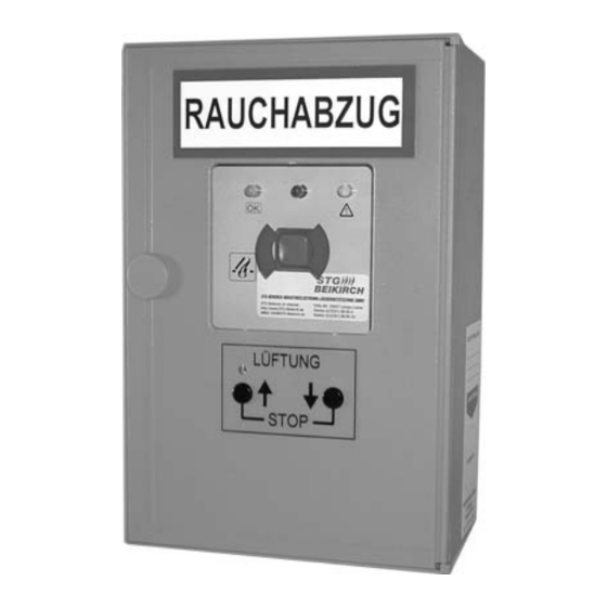
Für Rauchabzug und tägliche Lüftung, für 24 V DC Linear- und Kettenantriebe
For smoke heat extraction and daily ventilation for 24 V DC linear drives and chain motors
VdS
G501004
Montagebeispiel
Installation example
Kettenantrieb 24 V DC
Chain motor 24 V DC
Linearantrieb 24 V DC
Linear drive 24 V DC
Autom. Melder
Smoke detector
Anschlussdose
Junction box
RAUCHABZUG
Steuerzentrale
control centre
RWA-Zu
Lüftung
STOP
1,4 m
zusätzliche Lüftungstaster möglich
additional vent switches possible
zusätzliche RWA-
Bedienstellen möglich
RAUCHABZUG
additional SHE
manual call
points possible
RAUCHABZUG
1,4 m
Diese Bedienungsanleitung für späteren Gebrauch bzw. Wartung aufbewahren.
Änderungen dienen dem technischen Fortschritt und bleiben vorbehalten. Abbildungen unverbindlich.
Datei:
Ti_TRZ_VdS_2A_dt_engl.cdr
Art.Nr. 25000032
Version: 4
valid from: 18.08.2007
Funktion
Rauchabzugsanlage, vorzugsweise für
elektromotorisch zu öffnende Treppen-
räume.
Zum Öffnen der Rauchabzugs-
klappen im Brandfall. Schließen der
Rauchabzugsklappen durch Reset-
Funktion.
Öffnen und Schließen für die tägliche
Lüftung. Rauchabzugsklappen* in Form
von Lichtkuppeln, Dachklappen oder
Fenstern mit Linear- oder Kettenantrieben
24 V DC.
* (im folg. Text kurz Fenster genannt)
Besonderheiten
• mit integrierter RWA-Bedienstelle und
Lüftungstaster
• Funktion "Tägliches Lüften"
• 1 RWA-Gruppe (RG) und 1 Lüftungs-
gruppe (LG)
• Stromversorgung 24 V, Notstromakkus
und Ladeteil, Parallelbetrieb, 72 Std.
Funktionserhalt bei Netzausfall
• Leitungsüberwachung der Melderkreise
(autom. Melder und RWA-Bedienstellen)
• Leitungsüberwachung der angeschlos-
senen Antriebe mit Überwachungsleit-
ung oder 2-Draht-Impulsüberwachung
• zuschaltbare Lüftungsautomatik,
Netz
Schließung nach 10 Min.
Mains
• akustische und optische Störmeldung
• separat abgesicherter Netzeingang
230 V AC / 50 Hz
• Kunststoffgehäuse für Aufputzmontage
• Abmessungen 220 x 145 x 85 mm
(Höhe x Breite x Tiefe)
• Unter-Putz Montagemöglichkeit mit
Wand-Blendrahmen
• verschließbare Tür
• entspricht dem Stand der Technik
(normenkonform)
• prozessorgesteuert
• vielfältige Anschlussmöglichkeiten
• VdS zertifiziert
Smoke extraction system preferably for
eletromechanical openings in stairways.
Opening of the smoke vent flaps in case
of fire. Closing of the smoke vent flaps via
Reset-function.
Opening and closing for daily ventilation.
Smoke vent flaps* as dome lights, folding
skylights or windows with 24 V DC linear
drives or chain motors.
* (hereafter referred to only as "windows")
• with integrated SHE manual call point
and vent switch
• function "daily ventilation"
• 1 SHE group and
• 24 V power supply, emergency power
batteries and charging unit, parallel
operation,
guaranteed in case of power failure
• line monitoring of alarm circuits (autom.
detectors and SHE man. call points)
• line monitoring of the connected drives
with monitoring line or 2-wire-pulse
monitoring
• adjustable automatic ventilation, closing
after 10 min.
• acoustic and optical malfunction alarm
• separately fused power input 230 V AC /
50 Hz
• plastic housing for surface mounting
• dimensions 220 x 145 x 85 mm
(height x width x depth)
• flush mounting option with facing frame
• hinged door, lockable
• conforms to current state-of-the-arts
standards
• processor controlled
• versatile connection facilities
• with VdS certificate
Please keep these operating instruction for future reference and maintance.
Subject to technical modifications. Diagram is not binding.
Function
Features
1 ventilation group
72 hours of functioning
D
GB
Advertisement
Table of Contents

Related Manuals for STG-BEIKIRCH RZ VdS 2A


Summary of Contents for STG-BEIKIRCH RZ VdS 2A
- Page 1 Ausgabe: 4 Gültig ab: 18.08.2007 Version: 4 valid from: 18.08.2007 Für Rauchabzug und tägliche Lüftung, für 24 V DC Linear- und Kettenantriebe For smoke heat extraction and daily ventilation for 24 V DC linear drives and chain motors Funktion Function G501004 Rauchabzugsanlage, vorzugsweise für Smoke extraction system preferably for...
-
Page 2: Safety Instructions
Sicherheitshinweise Safety instructions Sicherheitshinweise, die Sie unbedingt beachten müssen, Please observe the following safety which are emphasized werden durch besondere Zeichen hervorgehoben by special symbols Vorsicht / Achtung / Warnung Caution / Attention / Warning Danger to persons due to electricity Gefahr für Personen durch elektrischen Strom Vorsicht / Achtung / Warnung Caution / Attention / Warning... - Page 3 Sicherheitshinweise Safety instructions Leitungsverlegung und elektrischer Anschluss nur durch Routing of cables and electrical connections only to be done by zugelassene Elektrofirma. Netzzuleitungen 230 V AC separat a qualified electrician. Power supply leads 230 V AC to be bauseits absichern. Netzzuleitungen bis an die Netzklemme fused separately by the customer.
-
Page 4: Description Of Operating
Funktionsbeschreibung Description of operating Manual activation in case of fire/smoke/alarm Manuelle Auslösung bei Feuer/Brand/Alarm Smoke heat extraction / opening windows Rauchabzug / Fenster öffnen Press the red OPEN switch at a SHE manual call point rote AUF-Taste in einer RWA-Bedienstelle drücken Fenster windows open completely the red LED display... - Page 5 Funktionsbeschreibung Description of operating LED display LED-Anzeigen In the SHE control centre and SHE manual call points In der Steuerzentrale in den RWA-Bedienstellen The green LED display - operating OK - is shining. It goes out Die grüne LED-Anzeige - Betrieb OK - leuchtet. Sie erlischt bei: in case of: - Netz- oder Akkuausfall - mains or battery failure...
-
Page 6: Montage
Montage Assembly Die Montage der Steuerzentrale mu in trockenem Raum The SHE control centre has to be installed in a dry room. The erfolgen. Die Montageorte der RWA-Bedienstellen und assembly places for the SHE manual call points and the vent Lüftungstaster müssen gut sichtbar und erreichbar sein (RWA- switches must be well visible and accessible (SHE call point = 1.4... -
Page 7: Installation
Installation Installation Anschlussleitungen von oben in das Gehäuse der Steuerzentrale Route the connecting cables into the control centre housing at the führen. Alle Anschlussklemmen sind steckbar und vor dem top. All connecting terminals are plug-in type and are to be Leitungseinklemmen abzuziehen. -
Page 8: Possible Connections
Anschlussmöglichkeiten Possible connections mehrere Antriebe, gesamt max. 2 A mehrere Lüftungstaster mit Sicht- mehrere Lüftungstaster Auf / Zu Stromaufnahme anzeige LTA 25 gemeinsam = Stop several drives total power several vent switches with several vent switches open / closed consumption max. 2 A visual display LTA 25 together = Stop Bei Anschluss von mehreren Antrieben unbedingt... - Page 9 Anschlussmöglichkeiten Possible connections * Aktives Endmodul im letzten oder einzigen autom. Linienabschluss: in der letzten oder einzigen RWA-Bedienstelle beiliegenden Melder oder einge- baut in BMA. Endwiderstand 10k ( ) einklemmen (Klemme 1/3). * Active end module in the last or only Line termination: connect provided 10k end resistor ( ) in the last or unique SHE autom.
- Page 10 Putting into operation and trial run Inbetriebnahme und Probelauf Ohne Netzspannung, ohne Akku Without mains voltage and without battery Alle Teile mechanisch und elektrisch auf feste Verschraubung und Check all parts mechanically and electrically for fully tightened auf Beschädigungen prüfen die Klemmen: Motor und screw connections and damage the terminals: plug in...
- Page 11 Inbetriebnahme und Probelauf Putting into operation and trial run With mains voltage, with battery Mit Netzspannung, mit Akku Akku-Stecker aufstecken der Akku-Stecker ist verpolungssicher. Plug on the battery connector the battery connector is Wird er gelöst, auf gleiche Polung achten. polarized.
- Page 12 Inbetriebnahme und Probelauf Putting into operation and trial run Test Notstrom Test emergency power supply Netz freischalten ie grüne LED - Betrieb OK - erlischt. Die Disconnect power supply the green LED - Operation OK - gelbe LED - Störung- blinkt. goes out.
-
Page 13: Troubleshooting
Störungshilfe Troubleshooting Display - operating OK - is not shining Anzeige - Betrieb OK - leuchtet nicht in the SHE manual call points and the control centre: in den RWA-Bedienstellen sowie Steuerzentrale: - a malfunction has occurred (see flash code) eliminate the - Störung steht an (siehe Beep-Code) Störung beseitigen. -
Page 14: Technische Daten
Technische Daten Technical data Betriebsspannung/Netzanschluss Operating voltage/power connection: 230 V AC / 50 Hz 230 V AC / 50 Hz (+/- 10%), separat abgesichert (+/- 10%), separately fused Stromaufnahme Netz: max. 0,6 A Current consumption mains: max. 0.6 A Leistungsaufnahme: ca.
Need help?
Do you have a question about the RZ VdS 2A and is the answer not in the manual?
Questions and answers