Advertisement
Quick Links
http://www.narda-sts.it
User's Manual
PMM FR4003
From 9 kHz up to 30 MHz
SERIAL NUMBER OF THE INSTRUMENT
You can find the Serial Number on the front panel of the instrument.
Serial Number is in the form: 0000X00000.
The first four digits and the letter are the Serial Number prefix, the last five digits are the
Serial Number suffix. The prefix is the same for identical instruments, it changes only
when a configuration change is made to the instrument.
The suffix is different for each instrument.
Document FR4003EN-80708-2.05 – Copyright © NARDA 2018
Sales & Support:
NARDA
Via Leonardo da Vinci, 21/23
Safety
20090 Segrate (MI) -
Test
Tel.: +39 02 2699871
Solutions
Fax: +39 02 26998700
S.r.l. Socio Unico
FIELD RECEIVER
Manufacturing Plant:
Via Benessea, 29/B
17035 Cisano sul Neva (SV)
ITALY
Tel.: +39 0182 58641
Fax: +39 0182 586400
Advertisement

Related Manuals for NARDA PMM FR4003


Summary of Contents for NARDA PMM FR4003
- Page 1 The first four digits and the letter are the Serial Number prefix, the last five digits are the Serial Number suffix. The prefix is the same for identical instruments, it changes only when a configuration change is made to the instrument. The suffix is different for each instrument. Document FR4003EN-80708-2.05 – Copyright © NARDA 2018...
- Page 2 NOTE: ® Names and Logo are registered trademarks of Narda Safety Test Solutions GmbH and L3 Communications Holdings, Inc. – Trade names are trademarks of the owners. If the instrument is used in any other way than as described in this User’s Manual, it may become unsafe.
-
Page 3: Front Panel
General safety considerations and instructions ………..…………………. EC Declaration of Conformity .....………………………………………….. 1. General Information Page 1.1 Documentation………………………………………………………………….. 1.2 Operating Manual changes……………………………………………………. 1.3 Introduction to PMM FR4003..………………………………………………… 1.4 Instrument Items………….…………………………………………………….. 1.5 Optional accessories……………….…………………………………………... 1.6 Main Specifications…………………………………………………………….. 1.7 Front Panel………………………...……………………………………………. 1.8 Rear Panel………………………………………………………………………. - Page 4 3 9010F Fast Page 3.1 Introduction to PMM 9010F.…………………………………………………… 3.1.1 Principle of Operation………………………………………………………… 3.2 Sweep Mode..…………………………………………………………………… Ultra Fast FFT scan….……………………………………………………………..3.2.1 Measure….……………………………………………………………………. 3.2.1.1 Frequency..………………………………………………………………….. 3.2.1.2 Level…….…………….……………………………………………………... 3.2.1.3 Input Attenuators and Preamplifier………………………………………. 3.2.1.4 Misc………………………...………………………………………………… 3.2.1.5 RF Output Generator…………………………………………………...….. 3.2.1.6 Detector……………………………………………………………………… 3.2.1.7 Conversion factor……………………………………………………...…… 3.2.2 Limit…………………………………………………………………………….
- Page 5 4 PMM Emission Suite software Page 4.1 FR4003 Operation method……………………………………………………. 4.2 Sweep mode..…………………………………………………………………... 4.2.1 Scan tab.………………………………………………………………………. 4.2.2 Frequency……………………………………………………………………... 4.2.3 Detector, Hold time and Limit..……………………………………………... 4.2.4 RBW…………………………………………………………………………… 4.2.5 Min Att…………………………………………………………………………. 4.2.6 Preamp………………………………………………………………………… 4.2.7 Preselector……………………………………………………………………. 4.2.8 Prompt start…………………………………………………………………… 4.2.9 Ancillary……………………………………………………………………….. 4.2.10 Worst………………………………………………………………………… 4.2.11 Undo…………………………………….…………………………………….
- Page 6 6. Applications Page 6.1 How it works……………………………………………………………….…... 6.2 Power switch…………………………………………………………………... 6.3 ESD risks……………………………………………………………………….. 6.4 Principles of operation……………………………………………..…………. 6.5 Antenna Factor…………………………………………………………..……. 6.6 Procedure of Calibration…………………………………………………..…. 6.7 Measuring the EMI Voltage………………………………………………..… 6.8 Related products …..……………………………………………………..….. 7. Updating firmware and Activation code Utility Page 7.1 Introduction……………………………………………………………………..
-
Page 7: Table Of Contents
Figures Figure Page Front Panel…….……………………………………………………... Rear Panel…….……………………………………………………..BP-02 Replaceable battery…………………………………………. PMM FR4003 Functional Block Diagram…………..……………... PMM 9010F initial screen…………………………………………… 2-10 Antenna parts and assembly……………………………………….. 2-11 Sweep…………………………………………………………………. Spectrum……………………………………………………………… 3-11 Operation method……………………………………………. Sweep mode screen.………………………………………………… Analyzer mode window……………………………………………… 4-11 Manual mode window……………………………………………..…... - Page 8 • The protective earth ground conductor shall not be interrupted intentionally. • To avoid electrical shock do not remove protections or covers of the unit , refer to qualified NARDA Servicing Center for maintenance of the unit.
- Page 9 Descrizione FIELD RECEIVER Description Modello PMM FR4003 Model è conforme ai requisiti essenziali delle seguenti Direttive: conforms with the essential requirements of the following Directives: Bassa Tensione 2014/35/EU Low Voltage Compatibiltà...
- Page 10 This page has been intentionally left blank Contents...
- Page 11 1 – General Information Enclosed with this manual are: 1.1 Documentation • a service questionnaire to send back to NARDA in case an equipment service is needed. • an accessories checklist to verify all accessories enclosed in the packaging. 1.2 Operating Instruments manufactured after the printing of this manual may have a serial number prefix not listed on the title page;...
- Page 12 1.3 Introduction PMM FR4003 is not only a simple Rod Antenna but incorporates also a powerful EMI receiver, fully CISPR 16-1-1, to measure conducted and to PMM FR4003 radiated interferences from 9 kHz up to 30 MHz, and can increase its performances when matched with PMM 9010F units (optional).
- Page 13 • Reversible screwdriver; • Operating manual; • PMM FR4003 Utility Software on Software Media; • Certificate of Calibration; • Return for Repair Form. PMM FR4003 can be used with several optional accessories, the most 1.5 Optional common being the following: accessories •...
- Page 14 1.6 Main Table 1-1 lists the PMM FR4003 performance specifications. The following conditions apply to all specifications: Specifications • The ambient temperature shall be -10°C to 60°C TABLE 1-1 Main Specifications 9 kHz to 30 MHz Frequency range Resolution 1 Hz <...
- Page 15 Auto calibration RP-02 series serial optical interface 115 kbaud Optic Fiber connection 9010F series high speed optical interface PMM Emission suite – PMM FR4003 Utility PC softwares dBm, dBµV, dBµA, dBpW, dBµV/m, dBµA/m, dBpT Display units With PMM Emission Suite SW 80 to 200 dB selectable dynamic range CISPR 16-1-1, MIL-STD 461G full compliant on board receiver.
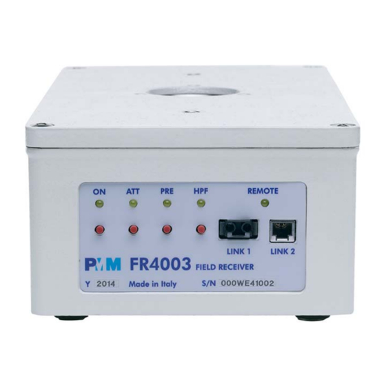
- Page 16 1.7 Front Panel Fig. 1-1 Front Panel Legend from left to right: - ON Push Button Power On Led; indicates the power status - ATT Push Button Attenuator Led; indicates the attenuator status It is off when the attenuator has been set to 0 dB it blinks shortly when the attenuator has been set to 10 dB it blinks half on and half off when set to 20 dB and it is permanently ON when set to 30 dB...
- Page 17 1.8 Rear Panel Fig. 1-2 Rear Panel Legend from left to right: - A OUT Analog Output, BNC female connector, 50 Ω - Batt Rechargeable Battery, PMM BP-02, with charger connector. The battery can be easily replaced or charged separately from the unit. - Power Supply Power Supply input to charge the battery.
-
Page 18: Pmm Fr4003 Functional Block Diagram
To be noted that during the FFT analysis the PMM FR4003 and 9010F make use of internal standard Gaussian filters, compliant to the standards, while in other cases it uses filters mathematically modelled to the perfection using a FIR technique. - Page 19 In this view the PMM FR4003 Field Receiver is the ideal solution from prototype debugging to final certification, as it fully meets all the performance criteria dictated by these standards, although it remains small, lightweight and very easy to use.
- Page 20 This page has been intentionally left blank 1-10 General Information...
- Page 21 Notify any damage to the forwarder personnel as well as to your NARDA Representative. To avoid further damage, do not turn on the instrument when there are signs of shipping damage to any portion of it.
- Page 22 Remove the two square foam inserts placed above the counterpoise. Remove the counterpoise from its custom foam insert holding on one side (do not use the central hole). Installation...
- Page 23 Remove the 1000 rod from its custom foam insert Remove the Carrying case from its custom foam insert Place the carrying case on a stable surface. Installation...
- Page 24 Open the carrying case and remove the Operating manual, Certificate of Calibration and Packaging Check list. Verify the availability of all the shipped items with reference to the Packaging Check list. Remove the 9010F and PC fiber optic. Installation...
- Page 25 Remove the calibration and counterpoise screw kit, the USB-OC Optical Converter, Software Media and the 40mm rod extension enclosed into the bag. Installation...
- Page 26 Remove the battery charger and all AC plug adapters enclosed into the bag. Installation...
- Page 27 2.4 Preparation for Use This is a Safety Class I apparatus. 2.5 Battery charger The battery charger supplied with the receiver can work at either 50 Hz or 60 Hz with a supply voltage rated between 100 and 240 Volt. It is supplied with different connectors to fit all the possible outlets in accordance with the various National standards.
- Page 28 To prevent any damage to the battery, the PMM FR4003 automatically switches off when the battery voltage falls below 6,5V. In order to keep the batteries fully functional, it is crucial to have a complete recharge before storing them for periods longer than 4 months.
- Page 29 “ON” button is kept pressed for more than 2 seconds, the instrument is switched automatically off. After having been switched ON, the PMM FR4003 boots with its internal BIOS and runs the firmware, which manages the receiver.
-
Page 30: Pmm 9010F Initial Screen
(in the 150 kHz to 30 MHz range), and it is insulated at least up to 1500V. All these probes have an insertion loss and a frequency response that can be stored in the memory of the PMM FR4003, so that the actual readings of the receiver can be automatically corrected by these characteristics values. -
Page 31: Antenna Parts And Assembly
The characteristics of these transducers are usually specified in the relevant standards (e.g. Military or Automotive Standards). Their use with PMM FR4003 is very easy, as it’s enough to enter their response with the frequency into the memory of the receiver to have the readings automatically corrected. - Page 32 This page has been left blank intentionally 2-12 Installation...
- Page 33 Switch on the FR4003 unit by pressing its power button, Wait for the Attenuator Led to start blinking, Switch on the PMM 9010F by pressing its power button Check the initial screen showing the results of the starting self-test. Document FR4003EN-80708-2.05 - © NARDA 2018 9010F Fast...
- Page 34 16.1.1 compliant measurement with 2-second hold time over the A band (9 -150 kHz with a 200Hz RBW filter) in less than 8sec. Be sure not to overload both PMM FR4003 and PMM 9010F: the input signals should not exceed the maximum levels indicated in the main specifications in chapter 1.
- Page 35 3.2 Sweep Mode The Sweep mode is used to operate the PMM 9010F as a scanning EMI receiver. To enter this mode press the Sweep soft key on the main screen to set the parameters for the scan. All the automatic settings (RBW, frequency step, etc.) refer to the CISPR standard.
- Page 36 The Sweep mode function is divided into five sub windows: • Measure • Limit • Display • Marker • Load Store Always use Esc button to return to the previous view/condition. 3.2.1 Measure The Measure button is used to set the scan parameters and to run the sweep.
- Page 37 3.2.1.2 Level The Level function has 5 sub-menus, each one with several options.. Pressing the Display button it is possible to set two parameters: the visualized Dynamic range(chosen between 80, 100 and 120dB) and the Reference Level, that can be increased or reduced by steps of 5dB within the range +80 dBμV to 135 dBμV (-25 to +30 dBm).
- Page 38 The output level can be set between 60,0 and 90,0 dBµV with 0,1dB steps using the RF OUT Level button. The internal generator is also used for self-calibration of the PMM FR4003. Turn Off the RF Output generator, if it is not used, while you are in Scan Mode.
- Page 39 3.2.1.6 Detector This menu allows the operator to select the most appropriate detector for the test. In Sweep mode the Peak, Average, RMS (Root Mean Square) and Quasi- Peak detectors are available, and can be selected, via the appropriate button. Hold time (ms) The Hold Time (expressed in milliseconds) represents the time the receiver uses to “take a snapshot”...
- Page 40 3.2.1.7 Conversion factor When using a transducer– a Voltage or Current Probe, an Antenna, etc. – its conversion factor must be added to the measured values. The Conversion factor may also take proper account of losses as cable loss, attenuators added externally to the receiver, etc. The PMM 9010F can handle these factors in an automatic way and directly correct the readings.
- Page 41 3.2.4 Marker Selecting this function a Marker is immediately enabled, and it appears on the screen as a small black pointing down arrow corresponding to the highest reading; simultaneously a small window shows up in the bottom left corner of the screen, indicating the actual frequency and level read by the marker.
- Page 42 3.2.5 Load Store Pressing this key allows the User to have access to the memory of the receiver enables storing number of different configurations/sweeps that depends on the parameters set on the receiver (i.e. the number of measured points). For example, using standard CISPR parameters it is possible to store up to 15 sweeps on the A+B band.
- Page 43 3.3 Analyzer Mode To enter in the ANALYZER Mode press the Analyzer soft key on the main screen. In this mode the receiver works as a Spectrum Analyzer maximizing the sweep speed. The analysis is done at the selected span frequency. The marker provides accurate measurement of the signals frequency and level;...
- Page 44 3.3.1 Frequency Allows the User to set the tuning frequency and also the Span. The Center frequency of the Spectrum window can be directly edited into the window or set by the arrow buttons or by the rotary knob, which frequency steps are set under the Manual mode.
- Page 45 3.3.2 RBW The Resolution Bandwidth command is used to select the bandwidth of the measuring filter. Seven bandwidth filters are available: • 200 Hz CISPR 16 shaped at -6dB • 9 kHz CISPR 16 shaped at -6dB • 3 kHz at -6dB •...
- Page 46 3.3.2.2 MIL-STD-461E To enable the MIL-STD-461E Filters use the 9010 Set code Utility. Activation Procedure (option) For further information on software installation refer to the “Updating firmware and Activation code Utility” chapter. Click on “9010 Set code Utility” (WRDONGLE.EXE) once for running the Set code program, so getting the following window: Copy the 40 Digit Serial Code in the Dongle Code Window and select the Write MIL-STD Dongle button.
- Page 47 3.3.3 Level The Level function has 5 sub-menus, each one with several options. Pressing the Display button it is possible to set two parameters: the visualized Dynamic range (chosen between 80, 100 and 120dB) and the Reference Level, that can be increased or reduced by steps of 5dB within the range +70 dBμV to 105 dBμV (-35 to 0 dBm).
- Page 48 Using 0 dB attenuation both PMM FR4003 and PMM 9010F has no input protection. This is a potentially dangerous condition for the input stage of the receiver. Use 0 dB attenuation only if you are very sure that your input signal is less than 1 V (or 120 dBμV).
- Page 49 Then it can also be used to transform the PMM FR4003 in an emitting antenna, helping a lot in calibrating and testing systems, other antennas etc.
- Page 50 3.3.3.5 Conversion When using a transducer to make a measurement – a Voltage or Current factor Probe, an Antenna, etc. – there is always the need to add to the measured values the conversion factor of the transducer in use. The Conversion factor may also take proper account of losses as cable loss, attenuators added externally to the receiver, etc.
- Page 51 3.5 Manual Mode The MANUAL mode is a very useful feature to manually control the receiver and to deeply investigate electrical signals modifying the parameters of receiver exactly as per the needs of the Test Engineer. It is possible, for example, to observe the signals exceeding the limits frequency by frequency;...
- Page 52 In this case it could happen that the PMM FR4003 sees a high input signal and therefore tries to set the proper attenuation automatically increasing the value or the input attenuators.
- Page 53 Please refer to the PMM Emission Suite User’s Manual for general information about the usage of the software. 4.1 FR4003 Operation The PMM FR4003 can operate as a powerful EMI receiver and can be swept step by step or FFT. The software automatically performs all operations for method setting the receiver in the selected method.
- Page 54 4.2.1 Scan tab There are three different way to start a new work section: - Highlight the name of the Sweep , enter a new name and confirm by pressing ENTER. - Select one of the rows with the “right mouse click” (the selected line will be highlighted and the Scan Tab window will appear), select Clear Table to delete all the settings and confirm with OK, then right click on the mouse to start selecting the default bands for each new row according to CISPR and...
- Page 55 4.2.3 Detector, Detectors The Detector box allows the operator to select the most appropriate Hold time and detectors for the test; in Sweep mode the Smart Detector(S), Peak(P), Limit Qpeak(Q), RMS(R), Average(A), Rms-Avg(N), and C-Avg(C) detectors are available. The Smart Detector is an innovative special function implemented in the PMM Receiver with the purpose of reducing the test time and increasing the productivity of the lab.
- Page 56 The Smart Detector function is not available with PMM 9010F since it is already fast enough to perform the full measurement. Limit Each emission standard has one or more limits the User shall comply with. The box allows to load and activate one limit with the simple click of the mouse;...
- Page 57 It is important not forget to manually change BNC cable connection at LISN device’s Line or switch the Antenna axis before starting the next sweep; a message will be displayed at the start of each sweep. For Antennas the resulting action will be only the addition of an Horizontal or Vertical notice stored with measurement settings, i.e.
- Page 58 Use 0 dB attenuation only if you are very sure that your input signal is lower than the maximum allowable for such a test condition. Before to apply an unknown signal to PMM FR4003 field receiver, use an oscilloscope or a wide band RF voltmeter to measure it. In any case, set Min.
- Page 59 In this mode the receiver works as a powerful Spectrum Analyzer. 4.3 Analyzer Mode The analysis is done at the selected span frequency. Entering Analyzer Mode the main screen will look like the following: Fig. 4-3 Analyzer mode window To switch into the Analyzer Mode, simply select the proper “Analyzer” Tab. After that you can start defining the settings included in the Analyzer Tab and in the Global Test Settings.
- Page 60 4.3.2 Analyzer Mode Detector Tab Settings This menu allows the Operator to select the most appropriate detector for the test. In Analyzer mode the Peak, Average and RMS (Root Mean Square) 4.3.2.1 Detector detectors are available and can be selected via the appropriate box. Hold time The Hold Time (expressed in milliseconds) represents the time the receiver uses to “take a snapshot”...
- Page 61 4.3.2.5 Tune Manual @ To deeply investigate and control the center Frequency, select the Tune Manual @ button (the value of the frequency shown depends on the center frequency set), you will then enter the Manual Mode where the levels corresponding to the detectors (Peak, AVG, and RMS) in use will be displayed both in analogue and in digital format;...
- Page 62 4.3.3.2 Limits Each emission standard has one or more Limits the User shall comply with. The box allows to load and activate one limit with the simple click of the mouse; the preloaded standard limits refer to the most popular EMC emission standards.
- Page 63 4.4 Manual Mode The MANUAL mode is a very useful feature to manually control the parameters of receiver exactly as per the needs of the Test Engineer and deeply investigate signals. It is possible, for example, to observe the signals exceeding the limits frequency by frequency, evaluating their levels measured simultaneously with different detectors (Peak, QuasiPeak, RMS-Avg, C-Avg, RMS, Average), etc.
- Page 64 4.4.1 Manual Mode Tab Settings 4.4.1.1 Parameter After having fixed the Step size (max. value 30.1), press the left and the right arrow keys to decrease or increase the frequency by the selected step. The center Frequency of the reading can also be directly edited into the Frequency window.
- Page 65 4.4.2 Manual Mode Global Test Settings 4.4.2.1 BW IF The Resolution Bandwidth command is used to select the bandwidth of the measuring filter. Several bandwidth filters are available: • AUTO CISPR • 10 Hz (MIL STD option when in conjunction with PMM 9010F) •...
- Page 66 Each emission standard has one or more limits the User shall comply with. 4.4.2.4 Limits The box allows to load and activate one limit with the simple click of the mouse; the preloaded standard limits refer to the most popular EMC emission standards.
- Page 67 4.4.3 Manual Mode Graph In manual mode the levels corresponding to the detectors in use are displayed both in analogue and in digital format, and exactly as for the other operating modes, all the relevant information are reported on the screen.
- Page 68 4.5 RMS-AVG Detector PMM FR4003 has been designed to allow the use of many kinds of detectors. 4.5.1 Introduction CISPR Standard has introduced the application of two detectors that are derived from the Root Mean Squared and from the Average ones.
- Page 69 Copy the 40 Digit Serial Code in the Dongle Code Window and select the Write RMS-AVG Dongle button. This message appears when the Dongle code is not valid. It will be shown the following message; press OK to confirm. The software will inform that the Dongle Code has been successfully stored. Press Ok to close the program.
- Page 70 Averaging is carried out with lowpass filters of the 2nd order (simulating a mechanical instrument). Be sure not to overload PMM FR4003: the input signal should not exceed the maximum level indicated in the main specifications in chapter 1.
- Page 71 It is also useful to perform the autocalibration of the antenna itself, by employing both the internal receiver and the signal generator. Document FR4003EN-80708-2.05 - © NARDA 2018 Utility, Calibration and Analog mode...
- Page 72 Once the utility is correctly installed, it can be run by simply clicking onto the FR4003Utility icon. The FR4003 must be connected to the PC, using the provided USB optical converter and the plastic optic fiber. The cover screen appears, showing two buttons, one to connect to the Field Receiver and the other to exit.
- Page 73 When everything is ok, the main screen is shown. Under the File menu there are the buttons useful to switch the Field Receiver off, and to exit the program. 5.1.2 Preferences The program language can be chosen under the preferences menu. 5.1.3 Tools The Tools menu includes the buttons to setup the Signal Generator, the Capacitance Meter, and to run the Auto-Calibration.
- Page 74 Click the Internal Generator icon to open the corresponding window, where it 5.1.3.1 Internal is possibile to set all the signal generator parameters, such as the Load, Generator Frequency and Level. A colored button allows to activate and deactivate the signal. 5.1.3.2 Cap meter The Capacitance Meter is a special tool useful to check the intrinsec capacitance of the Rod or any other transducer connected to the N input.
- Page 75 A message pops up asking for the confirmation if the User is sure about running the calibration procedure. Utility, Calibration and Analog mode...
- Page 76 Once the calibration has started, please follow the steps below: 1) Make sure no device (antenna, cable, adapter) is connected to the N input 2) Click the Open box and wait for the measurement is taken. 3) When the Open text becomes black, connect the 50 Ω to Rod (Calibrator) fixture and click the Calibrator box, then wait again for the measurement is taken.
- Page 77 5.1.3.3 Auto-Calibration To run the Auto-Calibration, simply click onto the corresponding icon. The following window appears. Then, please click Start auto calibration If the Rod antenna, or anything else is connected to the N input, the receiver is able to detect it and the following message will popup. Utility, Calibration and Analog mode...
- Page 78 If the calibration starts correctly, a window opens showing the progress of the procedure. The calibration routines take a couple of minutes to complete. The resulting tabled values are the calibration factors the User needs to adopt when using the antenna in Analog mode. 5.1.4 Information Clicking the desired icon it is possible to read some interesting information and telemetries of the instrument.
- Page 79 The temperature of the internal circuitry is also available, and displayed in degrees Celsius. Clicking onto the ? (information) icon, the following useful window appears, showing the versions of all the softwares and firmwares. This function is very helpful, for example after a firmware upgrade, to check if everything has gone as expected.
- Page 80 150 kHz High Pass Filter (0.15 to 30 MHz range) Preselector filter not active (Off) No attenuation (0 dB) The settings can be modified also without the need of a PC connection, using the buttons on the front panel of the PMM FR4003. 5-10 Utility, Calibration and Analog mode...
- Page 81 Press the ON button for a short time to switch on the unit. 5.2.1 Front panel Keep the ON button pressed for a few seconds to switch off the unit. buttons The ON/OFF status is indicated by the corresponding Led lamp. Press this button to select the desired output attenuation.
- Page 82 This page has been left blank intentionally 5-12 Utility, Calibration and Analog mode...
- Page 83 6 – Applications PMM FR4003 is an active, high sensitivity Electric field receiving antenna. 6.1 How it works It has a built in preamplifier. It works as a short monopole over a ground plane. Its intrinsically high impedance within the covered frequency band is transformed and normalized by the internal preamplifier.
- Page 84 6.6 Procedure of PMM FR4003 is calibrated in accordance with the equivalent capacitive Calibration substitution method, using equipment which certifications traceability to national and international standards are reported on the antenna certificate itself. ElectroMagnetic Interference (EMI) voltage measurements on power 6.7 Measuring the...
- Page 85 7.3 Preparing the Turn off the PMM FR4003 and connect the optic fiber from the USB-OC, connected to the PC, to the FR4003 LINK 1 port. The USB-optical Hardware converter and the plastic optic fiber are supplied with the apparatus.
- Page 86 Run the FR4003SeriesUp Setup. Then, please follow the on-screen indications. Updating Firmware...
- Page 87 To obtain firmware or software updates for FR4003, please contact your NARDA distributor or download it directly from the NARDA Web site: www.narda-sts.it. PMM software is now installed in your PC, you can remove it, if needed, simply running the proper “Uninstall”...
- Page 88 Click on “FR4003SeriesUp” (FR4003SeriesUp.exe) once for running the update program, so getting the following window: Now, press the USB key, and follow the instructions. Three firmware components can be updated by this application: Firmware which is the receiver internal program, FPGA (swept method) to update the internal programmable logic and FPGA (FFT method) to update the internal programmable logic.
- Page 89 Be sure the batteries of PMM FR4003 and connected Laptop (PC) are fully charged before performing the FW Upgrade, otherwise the upgrade progress could not terminate properly. Alternatively, be sure to have both PMM FR4003 and Laptop (PC) powered through their respective AC/DC power adapters.
- Page 90 The program will display the following window: 7.5 To transfer data To start the process simply switch PMM FR4003 on, select Update Firmware or Update FPGA button, and wait until the automatic transfer is completed. During the firmware storing procedure, a blue bar will progress from left to right in the window of the PC, showing percentage of downloading, time by time, until 100%.
- Page 91 It is now possible to disconnect the cable connected to the PC, with the PMM FR4003 field receiver either switched On or Off. To obtain up-to-date Firmware or PC Utility for PMM FR4003, the User can contact his NARDA distributor or download it directly from Support area of EMC Product Range on the following Web Site: www.narda-sts.it.
- Page 92 The WrDongle utility allows to enable the function ordered such Options using the 40 Digit Activation Code received from NARDA Italy. Turn on the PMM FR4003 and connect it to a free USB port of the PC. Browse for All Programs from the Start Menu and reach the “WrDongle”...
- Page 93 The program will display the following window: Copy and paste the 40 Digit Activation Code to the “Dongle Code” input field and press the button below related to the specific Option: In case of failure, an error message is showed instead. Always cycle OFF and ON the receiver to properly initialize the function.
- Page 94 This page has been left blank intentionally 7-10 Updating Firmware...
- Page 95 (115200 N 8 1). 8.3 Protocol Be aware that only the PC can send the commands. PMM FR4003 will answer when is inquired only. The communication uses strings with variable byte width. The characters used inside the strings are in ASCII format (00 - 127) at 7 bits.
- Page 96 8.7 List of commands Query COMMANDs Syntax Function ?AAT* Sends back a string expressing the Attenuator status for Analyzer mode Sends back a string expressing the Center frequency for analyzer mode ?ACE* Sends back a string expressing the detector used for Analyzer mode ?ADT* ?AHT* Sends back a string expressing the Hold Time for Analyzer mode...
- Page 97 Setting COMMANDs Syntax Function Aborts a sweep currently in progress ASBK ASPA Suspends a sweep currently in progress ASRE Resumes a sweep previously paused Sets the FR4003 for Swept operation method #CHGS* Switches the 30 dB attenuator on the FR4003 according to ‘A’, ‘B’, N SA30A SAAT a Sets Attenuator for Analyzer Mode...
- Page 98 IDLE COMMANDs Syntax Function Sends back a string expressing current Att10 status ?IA1 ?IAT Sends back a string expressing the current Attenuator status. ?IAE Sends back a string expressing the current 20dB Extra Attenuator status. Sends back a string expressing current CAP-METER status. ?ICM Sends back a string expressing current 150kHz High-Pass filter status.
- Page 99 8.7.1 QUERY Commands Description ?AAT This query command #?AAT * sends back a string expressing the Attenuator status for Analyzer mode. The reply is made of 2 fields: • AAT =AUTO (FR4003 automatically selects the most suitable attenuator to get best dynamic range) or AAT =MAN (operator selects manually the attenuator) •...
- Page 100 ?BAT This query command #?BAT* sends back a string containing the battery information. BAT=V.vv;Flag Where V.vv is the voltage of FR4003 battery and is expressed in Volt. When the FR4003 is under recharge, V.vv becomes the string *** Flag can have both ‘1’ or ‘0’ value and it is intended for knowing whether the value has been refreshed since it was last read.
- Page 101 ?IDN This query command #?IDN* sends back a string containing information about model, release and date of firmware. Note that two <LF> are appended to the string before the terminator Example of reply: IDN=FR4003-FW - 1.12 20/10/059<LF><LF> (swept method) Example of reply: IDN=FR4003F-FW - 1.12 20/10/059<LF><LF> (FFT method) ?MAF This query command #?MAF* sends back a string expressing the tuning frequency, in exponential notation, for manual mode.
- Page 102 ?S/N This query command #?S/N* sends back a string containing serial number internally stored by manufacturer. Example of reply: S/N=000WE50327 This query command #?SAT * sends back a string expressing the Attenuator ?SAT status for Sweep mode. The reply is made of 2 fields: •...
- Page 103 ?SRT This query command #?SRT* sends back a string expressing the Start frequency, in exponential notation, for Sweep mode. Unit is fixed MHz. Example of reply: SRT = 1.500000e+07 which means that the start frequency in Sweep mode is 15MHz ?TAT This query command #?TAT * sends back a string expressing MinAtt value.
- Page 104 CHGS=OK; this is procedure take about 4 seconds. The Remote LED blinks fastly. Note: Once switched OFF, the PMM FR4003 returns to FFT method. This setting command switches the 30 dB attenuator on the FR4003, according to SA30A the last character, which can be ‘A’, ‘B’, or anything else.
- Page 105 This setting command sets the detector for Analyzer Mode. The argument (b) should SADT b be a index representing the detector as follows: 1 Peak 2 Avg 3 Rms The reply is SADT =OK which acknowledges the command has been granted or SADT =SERR if the command has been ignored.
- Page 106 0 uses the factor temporarily • name which is a string representing the name of it This command is intended for creating a conversion factor into PMM FR4003. For further information see command SCFW. When the command is received the conversion factor...
- Page 107 • lev Is the level of the limit and is expressed in dB The procedure to creating a conversion factor on PMM FR4003 is the following: • Send as many commands as the frequency points of limit are in upwards order.
- Page 108 The purpose of this command is to have a double value limit that can be used along with smart detector function when sweeping by the command SSFD: The procedure to set a custom double value limit on PMM FR4003 is the following: •...
- Page 109 Sending a LIE with no argument (Limit name) deactivates all limit active, if any. This command is intended for making a custom limit into the PMM FR4003. For further information see command SLIW.
- Page 110 Send as many commands as the frequency points of limit are, in upwards order. • Terminate (and make it active) by sending the command SLIE Here is an example how to make a custom limit on PMM FR4003: • #SLIW 0, 150e3; 66 * Send the first line 150kHz 66 dBµV •...
- Page 111 This setting command sets Attenuator, for Manual Mode, to the value indicated by SMAT a (a) which can be 0 in step of 10 dB. Automatic Attenuator feature is disabled. If (a) is a negative figure then the Automatic Attenuator feature is turned on. The reply is MAT=OK which acknowledges the command has been granted or MAT =SERR if the command has been ignored.
- Page 112 SSDOE --> Force to have 1 MHz RBW throughout the sweep During the sweep, for each step tuned, the PMM FR4003 sends a character 0x2E (“.”). At the end, if not aborted by as the command ASBK, the string “SWP_END” is sent to notify that the sweep has been done and available for uploading by the command “?FSF 0”.
- Page 113 SSFD Note: Please look at §8.8 for further details related to FFT operation method FreqStart; FreqStop; Arguments are as follows: • FreqStep; FreqStart = Sweep Start Frequency expressed in Hz Detector; • FreqStop = Sweep Stop Frequency expressed in Hz HoldTime;...
- Page 114 (Continued) • MinAtt = Minimum attenuation allowed during sweeping. This parameter SSFD ranges from 0 (no limitation) to the maximum the FR4003 can set. This FreqStart; parameter is normally used to avoid switching up the sensitivity in order FreqStop; to either protect the input from high spikes or to prevent switching down FreqStep;...
- Page 115 (Continued) • SFD=ERR 4<RC><LF> An Error was found in HoldTime value. SSFD HoldTime is either too big (>10s) or negative. FreqStart; • SFD=ERR 5<RC><LF> An Error was found in RBW. Errors can be one FreqStop; of the following: FreqStep; Unsuitable RBW for the active unit (for instance 200Hz Rbw Detector;...
- Page 116 (Continued) FFT will be used, as opposed to standard sweep step by step, when the following SSFD conditions are matched: FreqStart; Detector is either FreqStop; Peak (only) and HoldTime < 50ms or FreqStep; SMART and an alternate detector. Stop frequency <= 150kHz Detector;...
- Page 117 • freq Is the frequency, expressed in Hz (exponential notation allowed), being written The procedure to make and use a Frequency-Scan-Tab on PMM FR4003 is the following: • Send as many commands SSFW as frequency points of table are in upwards order.
- Page 118 SSPS a This setting command switches Preselector, for Sweep Mode, according the parameter (a) which can be either On or OFF. The reply is SPS=OK which acknowledges the command has been granted or SPS =SERR if the command has been ignored. Example: #SPS ON* Example: #SPS OFF* This setting command sets the Start frequency for Sweep mode.
- Page 119 8.7.3 IDLE The Idle commands are specific for the PMM FR4003 Field Receiver and related Commands to its behavior as active Rod antenna. Query and setting commands are described together. Description ?IA1 This query command #?IA1* sends back a string expressing current Att10 status.
- Page 120 ?ITG This query command #?IAE * sends back a string expressing the current internal Tracking Generator to the mode status. The reply reflects its status and can be: • ITG=Off • ITG= TGout • ITG=TGin For details on TG Mode please read the relative documentation. SIA1 a This setting command immediately switches then 10dB attenuator according to the parameter (a) which can be either On or OFF.
- Page 121 This setting command immediately selects the preselector to the index (a) as SIPS a follows: • 0: OFF • 1: 9kHz-5.67MHz • 2: 5.67MHz-11.19MHz • 3: 11.19MHz-16.71MHz • 4: 16.71MHz-22.23MHz • 5: 22.23MHz-30MHz The reply is IPS=OK which acknowledges the command has been granted or IPS =SERR if the command has been ignored.
- Page 122 8.7.4 Analyzer The PMM FR4003 replies to the command “SAGO” sending back an array of bytes reply which contains all the information needed to draw a sweep. Typically, the user should first send the PMM FR4003 all the setting commands to insure the receiver is correctly set on the wanted parameters and then read the reply.
- Page 123 ********** End of Header ********** (continued) From here all figures represent the level referred to the tuned frequency And are expressed in hundredth of dBm Level Fstart Little Endian 16 bit integer representing the level referred to start frequency. Level Fstart Little Endian 16 bit integer representing the level referred to start frequency +Fstep plus step frequency...
- Page 124 8.8 Special notes for FFT method When switched ON the PMM FR4003 runs in FFT method. For changing from FFT to Swept operation send the setting command #CHGS* Swept and FFT communication protocols are very similar one each other, with some improvements and extensions.
- Page 125 • Humidity (without condensation) 9.4 Return for repair When the Accessories need to be returned to NARDA for repair, please complete the questionnaire appended to this User’s Manual, filling in all the data that will be useful for the service you have requested.
- Page 126 PMM TR-01A Set (optional) 9.6.1 TR-01A Set Using the TR-01A Set, the antenna height can be adjusted so that the counterpoise is level with the ground plane height (80-90 cm, or 100 cm above the floor, depending on the standard); or, the antenna can be lowered so that the center point of the rod element is 120 cm above the chamber floor, as required by MIL-STD-461G.
- Page 127 TABLE 9-2 Column strenghthner Specifications The Column strenghthner allows to • Dimensions Ø50 x 80 mm mount the FR4003 on the PMM TR- 01 Wooden tripod with extension • Weight 184 g • Load capacity 10 kg Fig. 9-3 Column strenghthner TABLE 9-3 Soft carrying case Specifications The Soft carrying case allows to •...
- Page 128 9.6.2 FR4003 installation on TR-01A Wooden tripod Legend: 1 – FR4003 2 – Column strengthener 3 – PMM TR01 Wooden Tripod Fig. 9-5 FR4003 parts and assembly Accessories...
- Page 129 Unscrew the pan-head screw from Column strengthener without losing it completely. Screw the Column strengthener on the FR4003 bottom; be sure that it is well locking Accessories...
- Page 130 Unscrew the plastic washer removing it completely from the TR-01. Install the PMM TR-01 Wooden Tripod on the site. Insert the Column strengthener (fixed to FR4003) on the wooden extension and make sure it is fully inserted, then screw the pan-head screw (be sure that it is well locking).
- Page 131 This section provides the information useful for a correct packaging in case the unit has to be returned for service to the factory or whenever you need to prepare the PMM FR4003 unit for shipment. The unit includes parts that are sensitive to mechanical shocks as well as heavy ones like the counterpoise.
- Page 132 Insert the battery charger and all AC plug adapters into the bag and place it into the carrying case as shown Insert the calibration and counterpoise screw kit, the USB-OC Optical Converter, the 40mm rod extension and Software Media into the bag and place it into the carrying case as shown 10-2 Packaging Instructions...
- Page 133 Place the 9010F and PC fiber optic into the carrying case as show: Place the Operating manual, Certificate of Calibration and Packaging Check list into the carrying case as shown: Packaging Instructions 10-3...
- Page 134 Close the carrying case. 10-4 Packaging Instructions...
- Page 135 Place the carrying case on its custom foam insert Place the 1000 Rod on its custom foam insert Place the counterpoise on its custom foam insert holding on one side (do not use the central hole). Packaging Instructions 10-5...
- Page 136 Place the two square foam inserts above the counterpoise and cover all items with the rectangular one . Close the box with packaging tape. 10-6 Packaging Instructions...
- Page 137 Moreover, we are continuously improving our quality, but we know this is a never ending process. We would be glad if our present efforts are pleasing you. Should one of your pieces of NARDA equipment need servicing you can help us serve you more effectively filling out this card and enclosing it with the product.
- Page 138 Suggerimenti / Commenti / Note: Suggestions / Comments / Note:...
Need help?
Do you have a question about the PMM FR4003 and is the answer not in the manual?
Questions and answers