Table of Contents
Advertisement
Advertisement
Table of Contents

Related Manuals for Juniper LTE Mini-PIM

Summary of Contents for Juniper LTE Mini-PIM
- Page 1 LTE Mini-PIM and Antenna Installation Guide Published 2020-04-09...
- Page 2 END USER LICENSE AGREEMENT The Juniper Networks product that is the subject of this technical documentation consists of (or is intended for use with) Juniper Networks software. Use of such software is subject to the terms and conditions of the End User License Agreement (“EULA”) posted at https://support.juniper.net/support/eula/.
-
Page 3: Table Of Contents
LTE Mini-Physical Interface Module Hardware Specifications | 7 Installation LTE Mini-PIM Installation and Configuration | 9 Installing the LTE Mini-PIM in a SRX Series Services Gateway | 9 Configuring the LTE Mini-PIM on SRX Series Devices | 14 Configuring the LTE Mini-PIM | 14... -
Page 4: About The Documentation
If the information in the latest release notes differs from the information in the documentation, follow the product Release Notes. Juniper Networks Books publishes books by Juniper Networks engineers and subject matter experts. These books go beyond the technical documentation to explore the nuances of network architecture, deployment, and administration. -
Page 5: Merging A Full Example
Merging a Full Example To merge a full example, follow these steps: 1. From the HTML or PDF version of the manual, copy a configuration example into a text file, save the file with a name, and copy the file to a directory on your routing platform. For example, copy the following configuration to a file and name the file ex-script.conf. -
Page 6: Documentation Conventions
commit { file ex-script-snippet.xsl; } 2. Move to the hierarchy level that is relevant for this snippet by issuing the following configuration mode command: [edit] user@host# edit system scripts [edit system scripts] 3. Merge the contents of the file into your routing platform configuration by issuing the load merge relative configuration mode command: [edit system scripts] user@host# load merge relative /var/tmp/ex-script-snippet.conf... - Page 7 Table 1: Notice Icons Icon Meaning Description Informational note Indicates important features or instructions. Caution Indicates a situation that might result in loss of data or hardware damage. Warning Alerts you to the risk of personal injury or death. Laser warning Alerts you to the risk of personal injury from a laser.
- Page 8 viii Table 2: Text and Syntax Conventions (continued) Convention Description Examples Italic text like this Represents variables (options for Configure the machine’s domain which you substitute a value) in name: commands or configuration [edit] statements. root@# set system domain-name domain-name Text like this Represents names of configuration To configure a stub area, include...
-
Page 9: Documentation Feedback
URL or page number, and software version (if applicable). Requesting Technical Support Technical product support is available through the Juniper Networks Technical Assistance Center (JTAC). If you are a customer with an active Juniper Care or Partner Support Services support contract, or are... -
Page 10: Self-Help Online Tools And Resources
JTAC hours of operation—The JTAC centers have resources available 24 hours a day, 7 days a week, 365 days a year. Self-Help Online Tools and Resources For quick and easy problem resolution, Juniper Networks has designed an online self-service portal called the Customer Support Center (CSC) that provides you with the following features: Find CSC offerings: https://www.juniper.net/customers/support/... -
Page 11: Overview
PART Overview LTE Mini-Physical Interface Module (Mini-PIM) | 2... -
Page 12: Lte Mini-Physical Interface Module (Mini-Pim)
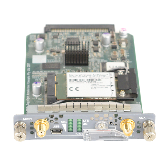
Storage support for multiple service provider and access point name (APN) profiles LTE carrier aggregation SIM lock and unlock capability Always-on, dial-on-demand, and backup modes Over-the-Air upgrade for modem firmware Figure 1 on page 2 shows the front panel of the LTE Mini-PIM. Figure 1: LTE Mini-PIM Front Panel... - Page 13 Mini-USB Type-B port for monitoring and troubleshooting. SIM slots Two slots, SIM1 and SIM2, for inserting the SIM cards. The LTE Mini-PIM supports mini, micro, and nano SIMs. The mini-SIM can be inserted directly in the SIM slot. To insert micro and nano SIMs, use the SIM adapters supplied with the Mini-PIM.
- Page 14 Table 4: Specifications for the LTE Mini-PIM Antenna (continued) Specification Value Operating frequency range 704~960 MHz 1710~2700 MHz Voltage Standing Wave Ratio (VSWR) 5 (maximum) Impedance 50 ohm Radiation Omnidirectional Peak gain 2.45 dBi (704~960 MHz) 4.51 dBi (1710~2700 MHz)
- Page 15 Dial-on-demand—The Mini-PIM initiates a connection when it receives traffic. Backup—The Mini-PIM connects to the 3G/4G network when the primary connection fails. The LTE Mini-PIM supports the following wireless standards: FCC Part 2 FCC Part 22...
-
Page 16: Lte Mini-Physical Interface Module Leds
Figure 3 on page 6 shows the LEDs on the LTE Mini-PIM. Figure 3: LTE Mini-PIM LEDs Table 7 on page 6 lists the LEDs on the LTE Mini-PIM and their indications. Table 7: LTE Mini-PIM LED States Description SIG (Received Signal Strength Indicator) Solid green (one bar)—Low signal strength (<= –99 dBm). -
Page 17: Lte Mini-Physical Interface Module Hardware Specifications
If all the LEDs are blinking, it indicates that firmware updates are in progress. Do not power off the services gateway before the updates complete. LTE Mini-Physical Interface Module Hardware Specifications Table 8 on page 7 provides the hardware specifications for the LTE Mini-PIM. Table 8: LTE Mini-PIM Hardware Specifications Description Value Dimensions (H x W x L) 0.80 in. -
Page 18: Installation
PART Installation LTE Mini-PIM Installation and Configuration | 9 LTE Mini-PIM Firmware Upgrade | 17... -
Page 19: Lte Mini-Pim Installation And Configuration
LTE Mini-PIM Installation and Configuration IN THIS CHAPTER Installing the LTE Mini-PIM in a SRX Series Services Gateway | 9 Configuring the LTE Mini-PIM on SRX Series Devices | 14 Installing the LTE Mini-PIM in a SRX Series Services Gateway... - Page 20 6. Slide the Mini-PIM in until it lodges firmly in the services gateway. See Figure 4 on page Figure 4: Installing the LTE Mini-PIM 7. Using a 1/8-in. (3-mm) flat-blade (–) screwdriver, tighten the screws on each side of the Mini-PIM faceplate.
- Page 21 NOTE: When you insert SIM cards into the respective slots, make sure to orient the cards correctly. Insert SIM1 into its slot with the connector side (SIM card chip) facing down and the notch on the left. Insert SIM2 into its slot with the connector side facing up and the notch on the right.
- Page 22 Figure 6: Attaching the Antennas The antenna base is magnetic and can be attached to the rack directly, if the rack is metallic. Else, you can mount the antenna base on the rack using the mounting brackets. See Figure 7 on page Figure 7: Mounting the Antennas on a Rack...
- Page 23 11. Power on the services gateway. NOTE: When a services gateway, with the LTE Mini-PIM installed and SIM card inserted, is powered on for the first time, it might take up to 10 minutes for the Mini-PIM to upgrade the modem firmware for the local LTE carrier.
-
Page 24: Configuring The Lte Mini-Pim On Srx Series Devices
To configure the Mini-PIM: NOTE: If a services gateway with factory-default settings is powered on with the LTE Mini-PIM installed in slot 1, the dialer interface is triggered to dial automatically. This functionality is applicable only if the Mini-PIM is installed in slot 1. If the Mini-PIM is installed in any other slot, then you will need to manually configure the cl-slot-number/0/0 interface to be associated with the dialer interface. -
Page 25: Configuring A Static Route On The Dialer Interface
NOTE: If a SIM card is installed in the second slot, then select the profile and configure the radio access type for the secondary SIM card as well. 5. Configure the dialer interface: Always-On mode: user@host# set interfaces dl0 unit 0 family inet negotiate-address user@host# set interfaces dl0 unit 0 family inet6 negotiate-address user@host# set interfaces dl0 unit 0 dialer-options pool dialer-pool-number user@host# set interfaces dl0 unit 0 dialer-options dial-string dial-number... - Page 26 route on the dialer interface by using the set interfaces dl0 unit 0 dialer-options route destination-ip-address command. After you configure a static route, make sure that the route appears in the routing table of the device by using the show route command. Note that the static route appears in the routing table only after the LTE Mini-PIM is connected to the network.
-
Page 27: Lte Mini-Pim Firmware Upgrade
CHAPTER 3 LTE Mini-PIM Firmware Upgrade IN THIS CHAPTER Upgrading the Mini-PIM Firmware Using the CLI | 17 Upgrading the Modem Firmware by Using OTA Upgrade | 20 Upgrading the Mini-PIM Firmware Using the CLI To upgrade the firmware on the Mini-PIM, using the CLI: NOTE: When you upgrade the firmware on the Mini-PIM, the modem firmware is also upgraded. - Page 28 The Current version field in the output displays the firmware version that is currently installed on the Mini-PIM. If there is a newer version of the firmware at https://www.juniper.net/support/downloads/?p=junos-srx#sw, then proceed to the next step to download the latest firmware.
- Page 29 user@host > request system firmware upgrade pic fpc-slot <fpc-slot-number> Part Type Tag Current Available Status version version FPC 1 PIC 0 MLTE_FW 17.2.91 17.5.517 Perform indicated firmware upgrade ? [yes,no] (no) yes Firmware upgrade initiated, use "show system firmware" to monitor status. 5.
-
Page 30: Upgrading The Modem Firmware By Using Ota Upgrade
Upgrading the Modem Firmware by Using OTA Upgrade Over-the-air (OTA) firmware upgrade enables automatic and timely upgrade of modem firmware when new firmware versions are available. The OTA upgrade can be enabled or disabled on the 4G/LTE Mini-PIM. OTA upgrade is disabled by default. - Page 31 Modem PIN security status: Disabled SIM status: SIM Okay SIM user operation needed: No Op Retries remaining: 3 4. Check the LTE Mini-PIM connection status: user@host > show modem wireless network cl-slot number/0/0 root> show modem wireless network cl-1/0/0 LTE Connection details Connected time: 147 IP: 172.16.52.4...
- Page 32 Reference Signal Receiving Power (RSRP): -97 Reference Signal Receiving Quality (RSRQ): -16 Signal to Interference-plus-Noise Ratio (SiNR): 0 Signal Noise Ratio (SNR): 0 Energy per Chip to Interference (ECIO): 0 RELATED DOCUMENTATION Upgrading the Mini-PIM Firmware Using the CLI | 17...
Need help?
Do you have a question about the LTE Mini-PIM and is the answer not in the manual?
Questions and answers